A simple line follower car or robot circuit can be built using the circuit explained in the following article. In this concept, the line follower car keeps track of a line underneath it and follows it meticulously as long as the line is extended.
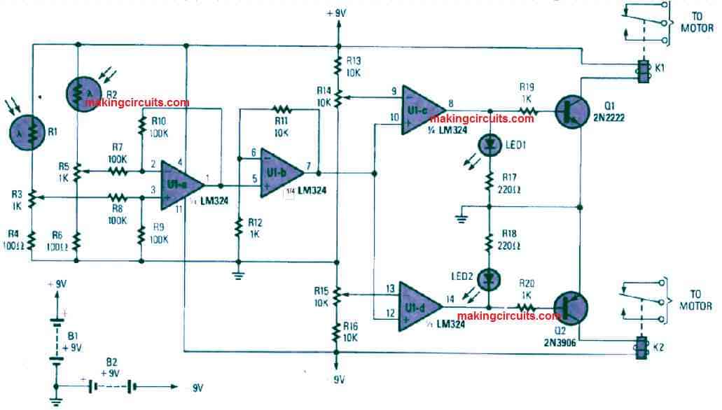
In this circuit 4 op amps from the IC LM324 are used.
U1a op amp is configured as a differential compartaor, whose both the inputs are connected with LDRs light sensors.
The LDRs are connected via adjustable presets, which are adjusted so that the LDRs produce uniform response on the input terminals of the op amp comparator when the light level is uniform on the LDRs.
However, if suppose the LDR R1 receives more light than LDR R2, this causes the voltage on pin3 of the op amp to increase which causes the output of U1a to become positive.
On the contrary, if LDR R2 receives more light than LDR R1, then the pin2 potential of the opamp increases causing the output of U1a to become negative.
So basically the the output of U1a flip flops between high and low logics in response to the differences between the light levels on the LDRs.
The next op amp U1b is simply configured like a voltage follower and amplifier, which follows and amplifies the output varying signals from the U1a output.
The next two op amp U1c and U1d are both configured as driver op amps.
When a positive signal is detected from the LDR comparators, due to an increased light on R1, this causes the non-inverting inputs of U1c and U1d to become positive, which in turn causes their outputs to turn high.
This high output from both the op amps causes Q1 to conduct since it is an NPN transistor, but the Q2 remains switched OFF since it is an PNP transistor.
Q1 switches on the connected relay which toggles its contacts so that one of the relevant motors switches OFF momentarily, which results in the vehicle or the line follower robots to correct its orientation so that both the LDRs receive the same amount of light.
In the other scenario if LDR R2 receives more light, it causes a negative voltage to develop on the non-inverting inputs of U1c, and U1d. This causes their outputs to turn negative, or 0 volts.
Due to this the NPN transistors now does not respond to the negative signal, but the PNP transistor responds and toggles it own connected relay.
The relay contacts switch accordingly and momentarily switches off the relevant connected motor until the line follower car or the robot adjusts automatically and corrects the light level on the LDRs, enabling the vehicle to run parallel with the line and to follow the line faithfully.
This circuit places a large reverse voltage across the Q1 and Q2 base-emitter junctions. This voltage exceeds the datasheet limits, and will lead to device failure. Also, the relay coils *must* have suppression diodes across the coils. Also, there is no power supply decoupling across the IC.
Thanks for pointing out the mistake…I agree, diodes are mistakenly not shown across the relay coils, if the diodes are connected then all reverse EMF problems will be solved…