This NiCd battery charger can easily recharge up to 8 NiCd cells hooked up in succession.
This quantity could be augmented in cases where the power source is raised by one.65v for every other cell.
In the event that the BD679 is installed on a quality heatsink, the input voltage could be improved to an optimum of 25v. The circuit would not discharge the battery when the charger is turned off from the supply of power.
In most cases NiCd cells needs to be fully charged at the fourteen hour rate. This really is a recharging current of 10% of the capability of the cell for 14 hrs.
This is true for a just about a fully discharged cell. As an example, a 600 mAh cell is fully charged at 60mA for fourteen hours. In the event that the re-charging current is excessive it will eventually ruin the cell.

The degree of charging current is regulated by the 1k pot from 0mA to 600mA. The BC557 is started up while NiCd cells are linked with the appropriate polarity.
Should you fail to get hold of a BD679, source another with any kind of NPN average power Darlington transistor containing a nominal amount voltage of 30v along with a current efficiency of 2A.
By decreasing the value of the one ohm resistor to 0.5 ohm, the highest possible output current tend to be boosted to 1A.
Hindi Translation
NiCd बैटरी चार्जर
यह NiCd बैटरी चार्जर आसानी से उत्तराधिकार में कांटे की शकल 8 NiCd कोशिकाओं को रिचार्ज कर सकते हैं। यह मात्रा शक्ति के स्रोत के हर दूसरे सेल के लिए one.65v द्वारा उठाया जाता है, जहां मामलों में संवर्धित किया जा सकता है। BD679 एक गुणवत्ता heatsink पर स्थापित किया गया है कि घटना में, इनपुट वोल्टेज 25V की एक अधिकतम करने के लिए सुधार किया जा सकता है। सर्किट चार्जर बिजली की आपूर्ति से बंद कर दिया है जब बैटरी का निर्वहन नहीं होगा।
ज्यादातर मामलों NiCd कोशिकाओं में पूरी तरह से चौदह घंटे की दर से शुल्क लिया जाना चाहिए। यह वास्तव में 14 घंटे के लिए सेल की क्षमता का 10% की एक रिचार्जिंग चालू है। यह एक बस के बारे में एक पूरी तरह से छुट्टी दे दी सेल के लिए सच है। एक उदाहरण के रूप में, एक 600 एमएएच सेल पूरी तरह से चौदह घंटे के लिए 60mA पर आरोप लगाया है। फिर से चार्ज वर्तमान घटना में है कि यह अंततः सेल को बर्बाद कर देगा अत्यधिक है। वर्तमान चार्ज की डिग्री 0mA से 600mA को 1K pot द्वारा नियंत्रित किया जाता है। NiCd कोशिकाओं उचित polarity के साथ जुड़े हुए हैं, जबकि BC557 शुरू कर दिया है। आप एक BD679 की पकड़ पाने 2A की मौजूदा क्षमता के साथ-साथ 30v की एक मामूली राशि वोल्टेज युक्त NPN औसत बिजली Darlington ट्रांजिस्टर के किसी भी प्रकार के साथ एक अन्य स्रोत को विफल करना चाहिए। 0.5 ओम, उच्चतम संभव उत्पादन चालू करने के लिए एक ओम बाधा का मूल्य कम करके 1 ए को बल मिला हो जाते हैं।
More NiCd Charger Circuits using BJTs
The pair of BJT based Ni-Cd charger circuits in the discussion here is recommended for existing battery-powered devices.
The first figure below depicts the absolute minimum as a standard current source. The reference voltage is received from the forward drop across LED D1 which is about 1.5 V for a red LED.
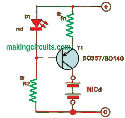
To make sure the voltage at the base of T1 is 1.5 V lower than the positive supply rail, resistor R2 limits the flowing current through the LED. The estimate of voltage across resistor R1 is 0.85 V.
This value can be applied to find out the charge current for the battery by using the formula:
IB = 0.85R1
Generally, the current is independent of the circuit supply voltage.
You can compute the value of R1 easily because almost all NiCd batteries are usually charged with a current 1/10 of their capacity. Table 1 represents a variety of battery types and their related R1 values.

It is important to note that LED D1 will turn off if there is no battery. This is because the voltage across R1 certainly falls and the LED current which is travelling via R2 will divert and run through R1 and T1’s base-emitter junction.
The detailed version of the NiCd charger circuit displayed in Figure 2 contains a diode to safeguard the circuit from being spoiled by wrongly polarised input voltages.
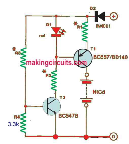
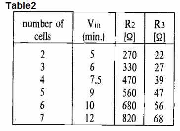
To deactivate the charger when an adequate high input voltage is not present, R3, R4 and T2 have been included in the circuit. From Table 2, you can see the values for R2 and R3, provided the number of 1.2 V cells fitted in the NiCd battery.
If the charge current does not cross the 100-mA mark, you can incorporate almost any type of PNP transistors in the T1 position. However, for better management of higher input voltages or change currents, use a medium-power transistor from the BD series.
Furthermore, there is no need for the input voltage to be extensively regulated or smoothened out. You may use any type of adapter yielding sufficient output voltage and current. The charge current may be gotten from a 12 V car battery based on the number of cells arranged in the NiCd battery.
The circuits we discussed can be built on a breadboard/protoboard to suit the devices in use. Just make sure the input voltage to the charge is connected to any household plug or socket.
Leave a Reply