• Skip to main content
  • Skip to primary sidebar

Making Easy Circuits

Learn and build electronic circuits

You are here: Home / Signal Processor / Simple Sawtooth Generator Circuit

Simple Sawtooth Generator Circuit

Last Updated on January 10, 2018 by Admin 2 Comments

The post explains how an efficient sawtooth generator circuit can be built using just a handful of ordinary parts such as BJTs and resistors.

Sawtooth generators are often recommended in many divisions of electronics. We for that reason include a new design for a circuit that makes use of components that you can get in about any container of add-ons (or ‘rubbish’ to unbelievers). The fundamental model of the circuit as demonstrated in figure 1 works with a 9 V battery as the supply.

The circuit by itself could be conveniently comprehended: capacitor C1 is linearly charged by constant current source T1, R1, P1.

Transistors T2 and T3 are employed as replacement for a silicon controlled rectifier (SCR) and in case you bear this in your mind, the circuit is relatively simpler to understand.

021


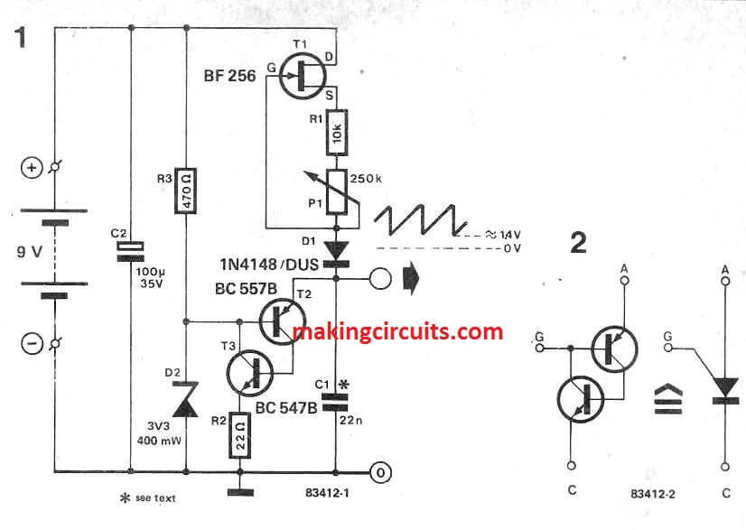
The ‘SCR’ is not really, as usual, fired by a pulse. Rather, the ’gate' is biased by voltage divider R3/D2 and when the ‘anode to cathode’ voltage surpasses this bias, the 'SCR' fires. C1 then discharges quickly via the ‘SCR’ and current limiting resistor R2.

Once the voltage across the capacitor has dropped to approximately 1.4 V, the current from the 'SCR' is becoming low enough for it to cut off. C1 once again charges and the routine repeats.

The ensuing sawtooth output voltage is demonstrated in figure 1. The frequency of the output voltage may be tweaked within a range of about 102 ; with the values proven the frequency range is 5...500 Hz.

The smaller C1, the more quickly it is going to charge, and the higher the frequency. The circuit was tested in our laboratories with frequencies up to 100 kHz, however higher frequencies are usually achievable.

The amplitude of the sawtooth voltage will depend on the ‘gate’ bias across zener diode D2 and it can consequently be changed by switching this diode. It will, however, be borne in your mind that tne zener voltage should not be over fifty percent the supply voltage to make sure appropriate functioning of the generator.

If an exponential ramp is necessary rather than linear one, T1 can basically be removed and R1 hooked up straight to the supply voltage. C1 will likely then charge straight from the supply and automatically offer an exponential waveform in this simple sawtooth generator circuit.

You'll also like:

  • 1.  Simple Voltage Controlled Oscillator Circuit
  • 2.  RC Passive and Active Filters Explained
  • 3.  Sine Wave Oscillator Circuit
  • 4.  Square Wave Generator Circuit with External ON/OFF Control
  • 5.  Understanding Phase shift Oscillator Circuit
  • 6.  Non-stop Newton’s Cradle Circuit

About Admin

Hey friends, Thanks a bunch for stopping by this site! I am an engineer with a Bachelor of Engineering in Electronics and Telecommunication. One of my passions is gathering information from all sorts of electronics books and tutorials. I then take that information and compile it into a language that is super easy to understand. My goal is to make those complex electronics circuit concepts and technical terms much more accessible for all the new and budding electronics engineers out there. I can also design customized circuit diagrams as required by the users.
If you have any questions related to this field, please do not hesitate to drop a comment! I am always here and ready to help you out with any queries you might have. I cannot wait to hear from you!

Reader Interactions

Comments

  1. Hildy says

    July 11, 2024 at 8:07 pm

    Hello. That is not an SCR in your schematic. It is a PUT, a type of Unijunction transistor. (The SCR diagram has the gate terminal on the cathode side.) It still works pretty much as you described. Once the Anode voltage exceeds the gate voltage (as set up by the voltage divider) it conducts and releases the stored energy of C1.

    Reply
    • admin says

      July 13, 2024 at 8:22 am

      You are right, thanks for the useful information.

      Reply

Leave a Reply Cancel reply

Your email address will not be published. Required fields are marked *

Primary Sidebar

Categories

  • 3 Phase (4)
  • 8051 Microcontroller (1)
  • Arduino (11)
  • Audio and Amplifier (102)
  • Automation (8)
  • Battery Chargers (64)
  • Bicycle Projects (4)
  • Car and Motorcycle Projects (39)
  • Datasheets (10)
  • DIY Projects (5)
  • Electrical (15)
  • Free Energy (6)
  • Games Projects (2)
  • High Voltage (14)
  • Hobby Projects (30)
  • Household Circuits (2)
  • IC 555 Circuits (5)
  • Ignition Circuits (2)
  • Indicators (50)
  • Infrared (6)
  • Inverter Circuits (29)
  • Lights and Lamps (97)
  • Medical (8)
  • Meter and Tester Circuits (38)
  • Motor Driver (17)
  • New Circuits (56)
  • Oscillators (30)
  • Pets and Pests (5)
  • Power supply (80)
  • Protection Circuits (25)
  • PWM (9)
  • Remote Control (20)
  • Security and Alarm Circuit (48)
  • Sensors and Detectors (66)
  • Signal Processor (23)
  • Solar Controller Circuits (62)
  • SSR (3)
  • Temperature Controller (20)
  • Timer (25)
  • Transformerless (7)
  • Transmitters (12)
  • Tutorials (45)
  • UPS (2)
  • Voltage Regulators (57)
  • Water Sensor and Controller (29)
  • Home
  • Privacy Policy
  • Contact
  • Disclaimer
  • Copyright

© 2025 · Making Easy Circuits