The article presents a simple yet extremely efficient smartphone charger circuit using a boost converter circuit. Let's learn the details.
A voltage booster DC, DC voltage multiplier, or DC-DC Step-Up Converter is a really valuable device that enables a low voltage reference to carry on to be activated (accelerated) to a higher output voltage that is a lot more useful.
For instance, high-brightness LEDs demand a 2.5-3.5 volts to light: possibly a couple of AA rechargeable batteries in series (1.2 + 1.2 = 2.4V) may not offer adequate voltage to activate the LEDs. The application of a voltage amplifier circuit of an LED could be driven by a single AA battery or some other power source - occasionally right down to 0.7 Volts!
This circuit works extremely well with low voltage solar power panels to create a little battery charger or to power directly a 5 volt device. Additionally it is mainly excellent to obtain usable voltages from tiny DIY stepper motor wind turbines yet again to recharge the batteries or LED light.
The source of the voltage booster circuit explained in this post is inspired from the original MintyBoost - a powered DIY device / recharging a USB device (for instance, then an iPod, and today iPhones and other smartphones) employing just a couple of Rechargeable AA batteries.
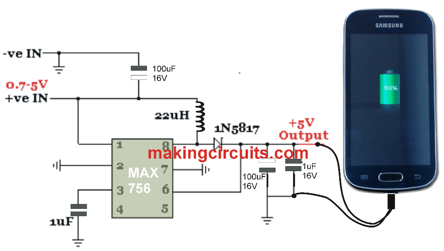
Converter MAX756 3.3V / 5V Step-Up DC-DC:
The important thing take into account in this voltage booster is the MAX756 - a MAXIM integrated circuit. This particular little chip boosts input supply voltages as little as 0.7 volts into a 3.3 volt or 5 volt output (user selectable) to up to 87% efficiency. The utmost output current is actually 200 mA which can be adequate for a broad variety of applications, which includes LED lighting, and the lowest input voltage is low makes it possible for the full capacity of the batteries to be utilized fully.
Making the DC-DC converter for charging smartphones
The below components are essential to create this 0.7 to 5 volts DC to DC converter using potentials and possibly prototyping or soldering tools and tips:
1 x MAX756
2 x 100uF capacitors
2 x 0.1uF Capactitors
1 x 1N5817 Schottky diode
1 x 22UH Power Inductor
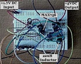
In the image shown above is the (not so photogenic) circuit finished on prototypying mock-up.
The above simple smartphone charger circuit was successfully tested with a couple of 'flat' AA rechargeable batteries. The complete battery voltage had been assessed at 2.21 volts, and the output voltage of the circuit had been tested at 5.00 volts using just one digital multimeter. The output voltage had been employed to power an ultrabright LED for 24 hours (by way of a current limiting resistor 270 Ohm) with no indications of dimming throughout this time around.
3.3V output of MAXC756
The above circuitry is utilized to induce DC voltages from 0.7+ Volts to 5.0 Volts. Simply by altering the input to pin 2 of the MAX756 from ground to positive, the output is triggered at 3.3 volts. This lets some LEDs to be illuminated without necessity for any series resistor or having a smaller resistance, so there exists much less waste of power by means of heat.
The Volt DC 3.3 output could furthermore be applied for Trickly charging a couple of AA batteries (in series) using the MAX756's 200mA current output.
For more information regarding the IC and the parts, you can refer to this datasheet of the IC
Leave a Reply