In this post we are going to construct a very simple inverter using Arduino Uno. The proposed project can be easily accomplished by beginners, but care must be taken since we are working with high voltage situation.
The project is made for arduino enthusiast; similar project can also be accomplished with transistors or IC 555 or IC 4047 etc. The advantage of using arduino is we can customize the output parameters, and mainly we can upgrade this square wave inverter to pure sine wave inverter by just writing a new code without any hardware changes (Program only given for Square wave).
If you are intermediate in arduino projects, you can easily tweak the hardware and code to add more features like low battery warning, automatic voltage correction, and quick automatic mains changeover and even you may add LCD display to show voltage readings and on-going status.
The Circuit:
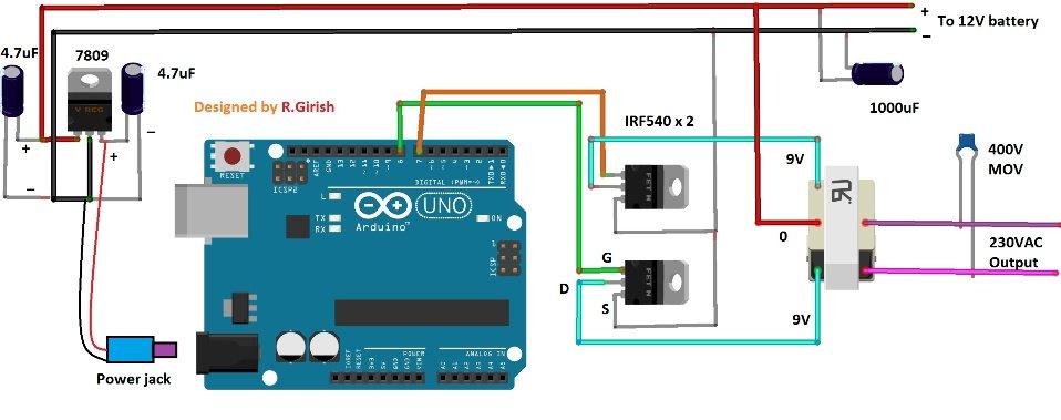
The simple inverter circuit consists of Arduino and you may choose your favorite arduino board. A voltage regulator LM 7809 which give constant voltage to arduino board regardless of battery voltage (Battery voltage must not drop below 11.90V).
The two capacitors connected to voltage regulator gives stability. The input capacitor 1000uF helps the inverter to start softly and provide immunity against sudden input voltage fluctuations.
Two MOSFETs are employed which can handle around 300 Watt power with heat sink mounted. If you want to more power you may choose more powerful MOSFET.
The transformer is a step down one, which is used in reverse to step-up the voltage and it its centre tapped. The transformer’s voltage and current parameter also decides maximum output power. You will need 30A transformer to get 270 watt power without considering efficiency loss.
You may also convert a microwave transformer and wind coils with experienced technician, but it is not recommended though.
Program:
- //-------------Program developed by R.Girish-----------//
- int out1 = 8;
- int out2 = 7;
- void setup()
- {
- pinMode(out1,OUTPUT);
- pinMode(out2,OUTPUT);
- }
- void loop()
- {
- digitalWrite(out2,LOW);
- digitalWrite(out1,HIGH);
- delay(20);
- digitalWrite(out1,LOW);
- digitalWrite(out2,HIGH);
- delay(20);
- }
- //-------------Program developed by R.Girish----------//
I like your explanation, thanks
Thank you Gabriel!
Mr. Swagatam, thanks for your awesome works!
please, I’ve seen the transformer is iron cored, isn’t it? Any modifications in circuitry and program lines, if I try to use ferrite cored pulse transformer, like pc switched power supplies? I intent to use IRF3205 or IRF260 MOSFET.
Again, thanks a lot
For ferrite core, the frequency will need to be above 20 kHz
How can we get the pure sine wave though the main function of the arduino here is to generate the pulse?. i would be grateful if the author could send us that code for improving the sine wave.
Sorry we don’t have the code for a sine wave inverter
My transformer has two wire in the primary coil and two wire in the secondary coil. Can i use this kind of transformer for making inverter? Thank you.
Hi, thank you for this projects, just one question, in the program you have delay on 20ms and delay off 20ms, so 40 ms per period which is 25Hz. For 50Hz the delays should be 10 ms, right?
Yes you seem to be right, please make it 10ms in the program code.
/*
This code was based on BARUTI SPWM code with changes made to remove errors. Use this code as you would use any other BARUTI ,s works.
11/6/2018
*/
const int sPWMArray[] = {500,500,750,500,1250,500,2000,500,1250,500,750,500,500}; // This is the array with the SPWM values change them at will
const int sPWMArrayValues = 13; // You need this since C doesn’t give you the length of an Array
// The pins
const int sPWMpin1 = 10;
const int sPWMpin2 = 9;
// The pin switches
bool sPWMpin1Status = true;
bool sPWMpin2Status = true;
void setup()
{
pinMode(sPWMpin1, OUTPUT);
pinMode(sPWMpin2, OUTPUT);
}
void loop()
{
// Loop for pin 1
for(int i(0); i != sPWMArrayValues; i++)
{
if(sPWMpin1Status)
{
digitalWrite(sPWMpin1, HIGH);
delayMicroseconds(sPWMArray[i]);
sPWMpin1Status = false;
}
else
{
digitalWrite(sPWMpin1, LOW);
delayMicroseconds(sPWMArray[i]);
sPWMpin1Status = true;
}
}
// Loop for pin 2
for(int i(0); i != sPWMArrayValues; i++)
{
if(sPWMpin2Status)
{
digitalWrite(sPWMpin2, HIGH);
delayMicroseconds(sPWMArray[i]);
sPWMpin2Status = false;
}
else
{
digitalWrite(sPWMpin2, LOW);
delayMicroseconds(sPWMArray[i]);
sPWMpin2Status = true;
}
}
}
Dear monojit halder
you can use this code and you have to use L298N Motor Driver as switching mosfet
connect transformers primary wire to motor1 + and motor1- in L298N and the arduino output pin connect to the logic pin on L298N in1 in2 and try to power all this things and also you have to connect 5v ang gnd from arduino to L298n may be this will works hope fully.
This will only generate a square wave signal.have done dis kind of design some years ago it keep heating up my mosfet and because of the lacking of feedback control the output will be very low less than 110v instead of 220v except you wind the transformer excessively at the secondary side
it is a square wave inverter, and mosfet will eat up if the output is overloaded or if the mosfet is not mounted on proper heatsink,
output will never be low if the trafo selection is as per the battery specs