• Skip to main content
  • Skip to primary sidebar

Making Easy Circuits

Learn and build electronic circuits

You are here: Home / Audio and Amplifier / Simple Stereo Amplifier Circuit using IC TDA2004

Simple Stereo Amplifier Circuit using IC TDA2004

Last Updated on November 16, 2024 by Admin 6 Comments

A very simple 10 +10 or in total 20 watt stereo amplifier circuyit has been discussed in this article using a single low cost IC TDA 2004 or a TDA 2005, using minimum number of components.

  • The main features which includes in this IC are:
    Low distortion.
    Almost zero noise.
  • The IC also features substantial stability of the of the package with supplemental essential safety measures throughout its functioning using the following protections:OUTPUT AC SHORT CIRCUIT TO GROUND
    EXTREMELY INDUCTIVE LOADS
    OVERRATING CHIP TEMP
    LOAD DUMP VOLTAGE SPIKE
    FORTUITOUS OPEN UP GROUND
  • Space and cost conserving : suprisingly low quantity of external parts,quite simple installation system without any electrical isolation amongst the package and the heatsink.The TDA2004A is actually a class B dual audio power amplifier in MULTIWATT bundle particularly created for stereo audio amplification purposes.tda2004 car battery stereo amplifier circuit
  • Simple Stereo Amplifier Circuit using IC TDA2004PARTS LIST
  • Resistors ( all are 1/4 watt 5%)
    R1= 1Ω
    R2= 1Ω
    R3= 1.2kΩ
    R4= 1.2kΩ
    R5= 3.3Ω
    R6= 3.3Ω
    R7= 120kΩ
    C1= 2200µF 16V
    C2= 2200µF 16V
    C3= 100µF 16V
    C4= 100µF 16V
    C5= 100nF (104)
    C6= 100nF (104)
    C7= 220µF 16V
    C8= 220µF 16V
    C9= 2.2µF 16V
    C10= 2.2µF 16V
    C11= 100nF (104)
    C12= 470µF 25V
    C13= 10µF 16V
    LS1, LS2= 4Ω 10W speaker
    IC1= TDA2004

With the part values displayed along with a supply voltage of 14.4V (a fully charged car battery), the stereo amplifier has the ability to of offering a power output of a minimum of 6W, normally 6.5W with a load impedance of 4Ω. It may also deal with a load impedance of 2Ω, whereby the output power is actually a the least 9W, but generally 10W. Power outputs with this arrangement are susceptible to about 10% distortion, nevertheless, if reduced power outputs are suitable, 4W with a load impedance 4Ω or 6W having a load impedance of 2Ω, distortion is barely within the limits of 0.3%.

The voltage gain of the left-hand channel depends upon the proportion of R3 to R5, as well as that of the right-hand channel through the percentage of R4 to R6. Using the values provided, this can be 50dB. Consequently, a signal of 50mV is necessary at the input to offer the optimum output. If this input sensitivity is really high, a 50kΩ stereo potentiometer could be integrated within the input. The impedance of non-inverting amplifier input is at the most 100kΩ.

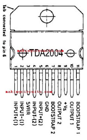
TDA2004 PIN Settings Top View

TDA2004 PIN Configuration-top-view

The system composed of resistor R1 and capacitor C5 (and R2, C6) is incorporated to avoid the amplifier getting unstable at higher input frequencies. The bandwidth of the circuit is higher than enough for proper use as a audio stereo amplifier. The frequency response of amplifier will be 40Hz to 16kHz (3dB level).

The IC needs to be maintained adequately cooled. The thermal resistance of the heatsink ought to be a minimum of 4°C/W.

TDA2004 Stereo Amplifier PCB Layout

TDA2004/TDA2005 20watt stereo amplifier PCB layout

You'll also like:

  • 1.  Guitar Effects Generator Circuit
  • 2.  24 Best Opamp Amplifier Circuits
  • 3.  Audio Signal Conditioner Circuit
  • 4.  Simple Electronic Bagpipe Music Generator Circuit
  • 5.  How to Make a Simple Musical Greeting Card
  • 6.  Electronic Bongo Circuit

About Admin

Hey friends, Thanks a bunch for stopping by this site! I am an engineer with a Bachelor of Engineering in Electronics and Telecommunication. One of my passions is gathering information from all sorts of electronics books and tutorials. I then take that information and compile it into a language that is super easy to understand. My goal is to make those complex electronics circuit concepts and technical terms much more accessible for all the new and budding electronics engineers out there. I can also design customized circuit diagrams as required by the users.
If you have any questions related to this field, please do not hesitate to drop a comment! I am always here and ready to help you out with any queries you might have. I cannot wait to hear from you!

Reader Interactions

Comments

  1. Viktor says

    February 1, 2023 at 2:13 pm

    Was bedeutet die anzeige von C 13, 1 60.Danke.

    Reply
  2. kabaka says

    March 22, 2021 at 1:43 pm

    mine is not working

    Reply
    • admin says

      March 27, 2021 at 11:11 am

      check it carefully, will work

      Reply
  3. Nuwan says

    March 6, 2020 at 12:44 pm

    V Good

    Reply
    • Yakup Durak says

      July 3, 2022 at 9:57 pm

      çalışmaz başkan her iki pcb ve şablon farklı dikkat edersen pcb üzerinde c12 yok yani pcb yanlış.

      Reply
      • admin says

        July 14, 2022 at 4:19 pm

        C11 C12 must be connected across the power supply lines on the pcb

        Reply

Leave a Reply Cancel reply

Your email address will not be published. Required fields are marked *

Primary Sidebar

Categories

  • 3 Phase (4)
  • 8051 Microcontroller (1)
  • Arduino (11)
  • Audio and Amplifier (102)
  • Automation (8)
  • Battery Chargers (64)
  • Bicycle Projects (4)
  • Car and Motorcycle Projects (39)
  • Datasheets (10)
  • DIY Projects (5)
  • Electrical (15)
  • Free Energy (6)
  • Games Projects (2)
  • High Voltage (14)
  • Hobby Projects (30)
  • Household Circuits (2)
  • IC 555 Circuits (5)
  • Ignition Circuits (2)
  • Indicators (50)
  • Infrared (6)
  • Inverter Circuits (29)
  • Lights and Lamps (97)
  • Medical (8)
  • Meter and Tester Circuits (38)
  • Motor Driver (17)
  • New Circuits (56)
  • Oscillators (30)
  • Pets and Pests (5)
  • Power supply (80)
  • Protection Circuits (25)
  • PWM (9)
  • Remote Control (20)
  • Security and Alarm Circuit (48)
  • Sensors and Detectors (66)
  • Signal Processor (23)
  • Solar Controller Circuits (62)
  • SSR (3)
  • Temperature Controller (20)
  • Timer (25)
  • Transformerless (7)
  • Transmitters (12)
  • Tutorials (45)
  • UPS (2)
  • Voltage Regulators (57)
  • Water Sensor and Controller (29)
  • Home
  • Privacy Policy
  • Contact
  • Disclaimer
  • Copyright

© 2025 · Making Easy Circuits