These simple circuits will allow the user to transform any single channel audio or a mono audio input signal into a synthetic or artificial stereo output which will sound like authentic and will simulate a true stereo response.
The stereo simulator circuit is designed to create a mono signal, originating from a mono audio and also to transform it right into a pseudo stereo signal. It does this by dividing the input into two signal paths and after that filtering every signal.
The high frequencies are usually provided with the left input of your respective stereo amplifier and also the low frequencies towards the right hand channel.
Hook up the stereo simulator to your stereo amp and to a mono signal source.The result from the circuit could be altered by access to the amplifiers' tone controls (providing a kind of width control) and also the balance control.
How it Works
The circuit is dependent on two second order filters designed around IC1(b) and IC1(d). IC1(b) is a low pass filter along with component values preferred to present a break point of around 2kHz IC1(d) is a high pass filter with, again, a break point of 2kHz.
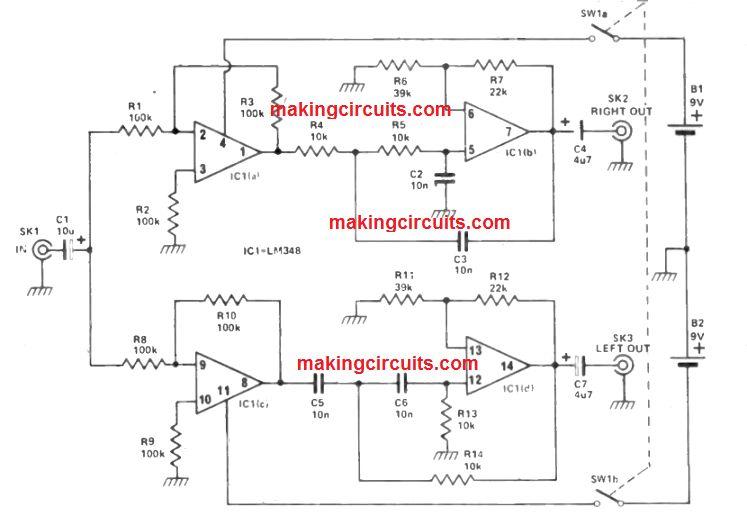
Hence the output at SK2 will incorporate the low frequency portion of the input (bass) and SK3's output will certainly include the high (treble) part of the input signal.
The mono input through SK1 is fed through unity gain input buffers to each filter element. This is certainly to prevent loading the filters which could break down their functionality.
Stereo Synthesiser
You will find there are usually two common techniques of designing a pseudo stereo effect from a mono signal; playing the mono signal through the two speakers in antiphase and also the use of frequency selective methods.
The latter usually includes directing lower frequency signals into one channel and higher frequency signals into the other. This specific circuit utilizes the second process, however can easily furthermore provide antiphase signals which could provide a much better result, particularly when making use of headphones.
Q1 is employed as an emitter follower buffer stage which usually makes certain that the two filter networks fed through its output tend to be driven from a low impedance source.
If these were driven direct through the input, it is rather possible that they could be fed from a source impedance of a few kilohms or even more, which might become pretty adequate to enhance their efficient qualities.

The two filters are usually created by R4 and C3 (low pass), and C6 plus R8 (high pass). A high roll -off rate through no means is actually important during this application and also the 6 dB per octave attenuation rate of simple RC filters for instance these types of are completely sufficient.
The -3 dB point of every filter is at approximately 800 Hz and also the combined output of the filter, as a result, provides a virtually flat reaction without any substantial peaks or troughs.
Q2 is linked as an emitter follower buffer stage which makes sure that there is certainly minimal loading within the low pass filter. Q3 in the same way makes certain that there is minimal loading on the high pass filter, although this device is utilized as a phase splitter.
Using SW2 switched to take the output via Q3's emitter, Q3 successfully functions as an emitter follower and provides no phase inversion. Along with SW2 switched to take the output from Q3's collector, Q3 then efficiently works as a common emitter stage with 100% negative feedback (and unity voltage gain) as a result of R11.
In addition, this stereo simulator circuit offers a 180° phase shift in order that the two output signals are usually in anti -phase. An in -phase relationship is required to provide a good central stereo image and the use of anti -phase signals tends to provide an impact of increased channel separation.
In a stereo orchestral recording it is actually normal for the violins to come from the left hand channel, with the cellos and basses from the right hand channel.
Consequently, the high frequency signals are fed to the left channel and the low frequency signals are fed to the right channel in order that the unit supplies a equivalent result (even though it may certainly perform effectively along with the outputs linked in any case). The current consumption of the circuit is around 3 mA.
Leave a Reply