This post explains how to build an easy transformerless power supply circuits. These circuits are compact and simple and they all use capacitors to step down the AC voltage from the mains without needing any transformers.
Transformerless power supply circuits take high voltage AC from the mains and convert it to lower DC voltage. They achieve this by using a special high voltage capacitor. This capacitor is crucial and needs to have a voltage rating thats higher than the peak voltage of the AC mains to ensure safe operation.
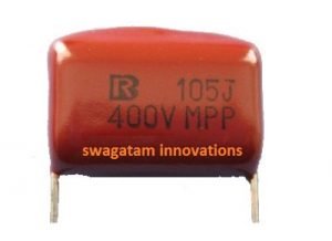
One example of a capacitor commonly found in transformerless power supply circuits is shown below:

The capacitor connects in series with the AC mains input, preferably on the hot (phase) line.
Its reactance limits the current flowing from the mains. However then the voltage isn't limited by the capacitor.
After rectification you'll measure a high peak voltage (around 310V) which can be alarming.
But there's a solution. A Zener diode at the rectifier output handles this high voltage by regulating it. Just make sure to choose the Zener diodes wattage based on the current allowed by the capacitor.
Warning
- These circuits are NOT isolated from mains power and can be deadly if touched while powered on.
- Extreme caution is required when testing or building them.
- Properly insulate all wiring, especially exposed connections.
- Only build these circuits if you have experience with mains AC safety.
Important Note:
- These circuits are designed for powering small, internal electronics and are not meant for powering external devices.
- Enclose the entire assembly in a well-insulated plastic box for maximum safety.
Understanding the Circuit:
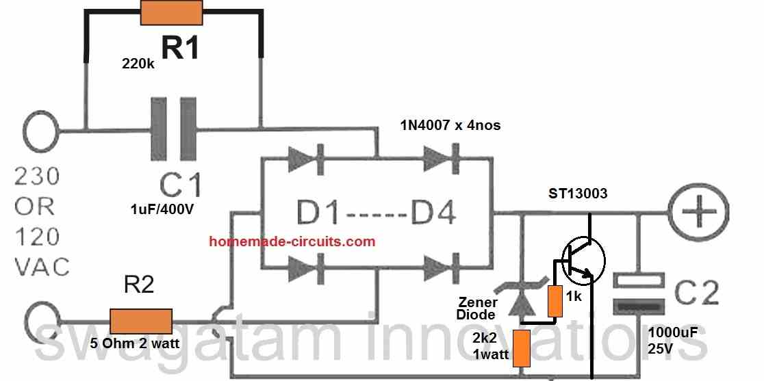
When you turn on the power, capacitor C1 acts like a current controller. It limits the current flowing from the mains based on its reactance (around 50mA in this example). However it doesn't affect the voltage. The full mains voltage (around 220V) reaches the bridge rectifier.
The bridge rectifier then converts this incoming AC voltage (220V) to a higher DC voltage (around 310V). This is because it's converting the AC's RMS value to its peak value. This high voltage might seem alarming, but the Zener diode comes to the rescue next.
The Zener diode acts like a pressure relief valve. Any voltage exceeding its set value (e.g., 12V for a 12V Zener) gets shunted to ground, regulating the output voltage to the desired level (12V in this case).
Finally, capacitor C2 takes the stage. It acts as a filter, smoothing out the remaining ripples in the 12V DC output, providing a cleaner power supply.
Basic Transformerless Design

Function of each Component
C1 - The Current Controller:
This capacitor acts as the first line of defense. It limits the high mains current (around 220V or 120V) to a lower level suitable for the output. As a rule of thumb each microfarad in C1 allows roughly 50mA for the load. So, a 2uF capacitor provides 100mA and so on.
R1 - The Safety Discharge Path:
This resistor is crucial for safety. When unplugged, C1 can store the mains voltage, risking a shock if touched. R1 discharges C1 quickly, preventing such mishaps.
D1-D4 - The AC to Low-Current DC Converter:
These diodes form a bridge rectifier. They convert the low-current AC coming from C1 into a pulsating low-current DC. While C1 limits current, it doesnt affect voltage. So, the bridge rectifier's output DC is the peak voltage of the AC (around 310V for 220V AC).
Zener Diode - The Voltage Regulator:
This diode regulates the high voltage (310V) to a desired lower level (like 12V, 5V) by shunting excess voltage, making it suitable for most low-voltage devices.
R2 - Surge Limiter and Current Limiter (Optional):
This resistor might seem redundant with C1 limiting current. However during initial power-on, C1 acts like a short circuit for a moment, allowing high current to flow. R2 prevents this surge from damaging the output by limiting current momentarily. A better option could be an NTC thermistor. NTC offers more precise current limiting.
C2 - The Smoothing Capacitor:
This capacitor filters out the ripples (100Hz) in the rectified DC from the bridge, providing a cleaner and smoother DC output. While a high voltage capacitor is shown, you can use a lower voltage one (like 220uF/50V) due to the Zener diode regulating the voltage.
Advanced Design Considerations
The simple transformerless design has downsides. Resistor R2 is crucial to protect the Zener diode, but it also reduces output current and wastes power due to heat dissipation.
Ideally we want a low R2 value for better efficiency while maintaining safety. Heres how a high-voltage transistor wired in a crowbar configuration can be used to reinforce the Zener diode. (Refer to the following diagram for details.)

The crowbar design appears fail-proof, offering a very stable output. The transistor acts like a safety switch. If the output voltage from the bridge rectifier tries to exceed the Zener diode level, the transistor conducts, shorting the circuit and grounding the power from capacitor C1. This rapidly drops the voltage.
When the voltage drops below the Zener threshold, the Zener stops conducting, turning off the transistor. This cycle repeats quickly resulting in a stable DC output voltage very close to the Zener diode's voltage.
Alternatively... if you dont want to use the transistor, you can modify the first design as explained below...

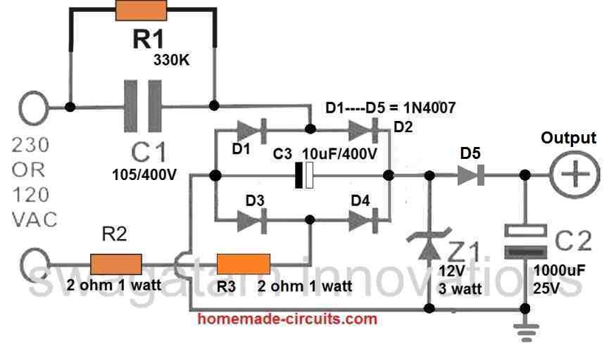
Three improvements were made to the circuit:
- Double Current Limiting: Two resistors (R2 and R3) share the surge current more evenly.
- Surge Absorption: Capacitor C3 grounds and absorbs the initial surge reducing stress on the Zener diode.
- Higher Zener Rating: A 3 watt Zener diode provides increased reliability.
For further improvement replace R2 and R3 with a single 5-ohm NTC thermistor for more precise current limiting.
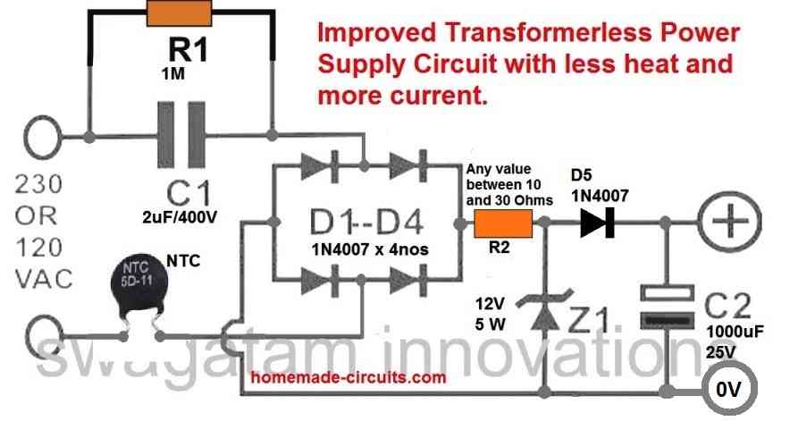
The design can be further enhanced with additional modifications explained below...

This modification removes the capacitor across the bridge rectifier.
This halves the load on the Zener diode, significantly reducing heat generation.
Additionally, the filter capacitor is now positioned after diode D5.
This placement lowers the capacitor's voltage to a safer 25V. This helps achieving a very high level of filtering, due to its increased value of 1000uF.
Another Simplest Design
This smart layout employs 4 diodes within a bridge to generate a predetermined voltage power supply efficient at delivering 35mA.
All diodes (all sorts of diode) are zener diodes. All of them malfunction at a specific voltage. The reality is, a power diode stops working at 100v or 400v and its zener attribute is simply not beneficial.
However we all place 2 zener diodes in a bridge along with 2 standard power diodes, the bridge will break-down at the voltage of the zener. This is exactly what we have accomplished. When we make use of 18v zeners, the outcome will probably be 17v4.
Once the inbound voltage is positive towards the top, the left zener offers 18v limitation (and the other zener constitutes a decrease of 0.6v) This allows right zener to secure current similar to a regular diode. The outcome is 17v4. Exactly the same using the other half-cycle.
The current is restricted through the value of the X2 capacitors which is 7mA for every single 100n when in full-wave (according to this circuit). We now have 1u capacitance. Hypothetically the circuit can offer 70mA however we discovered it is going to just deliver 35mA prior to the result declines. The capacitors ought to adhere to X1 or X2 class. The 10R is a safety-fuse resistor.
The issue with this power supply may be the "live" aspect of the negative track. Once the power supply is attached as demonstrated, the negative rail is 0.7v over neutral. When the mains is changed direction, the negative rail is 340v (peak) over neutral which will probably obliterate a person as the current will probably stream through the diode and be deadly. You should touch the negative rail (or the positive rail) and virtually any earthed gadget for instance a toaster to get mortally wounded. The sole option would be the venture becoming driven has to be completely encapsulated within a container without any outputs.
A TRANSFORMERLESS POWER SUPPLY is also called a CAPACITOR dependent or fed POWER SUPPLY.
It is extremely hazardous.
Here's the reason why:
A Capacitor Power Supply runs on the capacitor in order to interface among a “high voltage supply” and a low voltage - called THE POWER SUPPLY.
Put simply a capacitor is positioned amongst a “high voltage supply” we name THE MAINS (between 110v and 240v) and a minimal voltage that could be 9v to 12v.
Despite the fact that a capacitor includes 2 discs that do not necessarily contact one another, a Capacitor Power Supply is an extremely hazardous undertaking, for two main factors.
You possibly will not believe electrical power can complete through a capacitor as it contains plates which often never contact one another.
However a capacitor functions within a different approach. A capacitor attached to the 220V/120V mains functions something like this:
Think about a magnet on one part of your door. On the reverse side we have a sheet of metal. While you slide the magnet up the door, the sheet of metal goes up as well.
Precisely the same with a capacitor. As the voltage on a single aspect of the capacitor goes up, the voltage in opposition is “pulled away from the ground” - and it also goes up too.
In case you remain on the floor and hold one particular terminal of the capacitor and hook up another to the lively side of the “mains,” the capacitor could “draw” 120v or 240v “out from the ground” and you will probably receive a shock.
Don’t bother to ask “how” or “why.” This is certainly a perfect easiest approach to identify the way you obtain a zap via a capacitor which involves a couple of plates.
If the capacitor “shorts” between the two discs, the 120v or 240v is going to be delivered to your power supply and create destruction.
Subsequently, when some of the parts in your power supply turn out to be open-circuit, the voltage on the power supply increases.
Nevertheless the most harmful characteristic of this type of power supply is reversal of the mains terminals.

The circuit is intended in order that the neutral terminal goes toward the earth of your power supply. This implies the lively is attached to the capacitor. Now, the fact that lively functions could this be:
The live terminal soars 120x 1.4 = 180v in the positive direction after which declines to 180v within the reverse path. Quite simply it really is 180v greater than the neutral line then 180v below the neutral.
With regard to 240v mains, this is 325v greater then 325v lower.
The neutral is coupled to the framework of your job of course, if you contact it, not much will take place. Will not increase or slide.
However assume you link up the power leads round the improper approach.
The active has become coupled to the framework and if an individual contact the chassis and a water pipe, you might receive a 180v or 345v jolt.
Honestly, that is the reason why a CAPACITOR dependent power supply should be entirely isolated.
At this point we come face to face with the query: So how exactly does a capacitor make a 12v power supply?
Whenever a capacitor is attached to the mains, one lead is climbing and plummeting.
Based on the scale the capacitor, it is going to permit current to move into and out of the other terminal.
If the capacitor is a substantial value, a higher current may pass into and from the lead. Furthermore, an increased voltage will permit a larger current to circulate.
This current is “taken out of the ground” and “moves straight into the ground.”
Will not range from mains. The mains merely: “has a bearing on” the movement of current.
Therefore we now have a circulation of current directly into and out of the capacitor.
In case you placed a resistor between the capacitor and “ground,” the quantity of current that can pass, is determined by 3 items, the amplitude of the voltage, the dimensions of the capacitor and also the acceleration of the increase and drop.
Whenever current runs by way of a resistor, a voltage grows along the resistor in case we opt for the proper value of resistance, we are going to obtain a 12v power-supply.
THE OUTPUT VOLTAGE
The OUTPUT VOLTAGE of most transformerless power supplies is going to be around 50% Greater than the mains voltage in case a LOAD is just not linked. You got it: The output of a 120v CAPACITOR POWER SUPPLY (transformerless power supply) is going to be around 180v and a 240v mains transformer-less power supply will be approximately 345v.
How would you obtain a 12v or 24v supply????
Functions similar to this: The transformerless power supply is a CURRENT based power supply. Quite simply we need to mention CURRENT magnitudes and not voltages.
For a bridge circuit (known as full-wave design) it is going to provide 7mA for each 100n. Assume we have 220n. We now have 15mA accessible.
We consider the 15mA and point out: Just how many v will establish around a 100R load? The solution = 0.015 x 100 = 15v. In case we work with 82R the voltage will probably be about 12v. When we apply 220R the voltage will likely be 33v. That's the way the output voltage is actually formulated.
Should you include one more 220n over the 220n, the voltages will probably be TWO TIMES. Is actually as basic as this.
Leave a Reply