• Skip to main content
  • Skip to primary sidebar

Making Easy Circuits

Learn and build electronic circuits

You are here: Home / Audio and Amplifier / Simple Treble Booster Circuit

Simple Treble Booster Circuit

Last Updated on June 23, 2020 by Admin 3 Comments

A treble booster circuit works extremely well by having an electric guitar (as well as electronic equipment) to enhance the larger order harmonics and present an even more "excellent" sound.

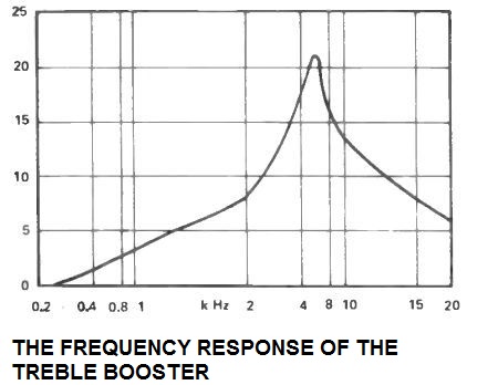
A circuit with this sort provides a relatively flat result at bass and many middle audio frequencies, while using upper middle and lower treble frequencies being provided a large amount of boost.

It really is regular to provide just a simple amount of focus to the upper treble so that you can provide great balance and a low noise level, which furthermore stops the output through sounding too unpleasant.

The frequency reaction of this treble booster circuit is demonstrated within the associated graph.
graph 1

How the Circuit Works

The treble booster circuit is actually merely an opamp (IC1) utilized in the non inverting amplifier mode. The non inverting input is biased through R4 and R5 by using a decoupling network which is certainly composed of R3 and C3. C4 and C5 provide DC obstructing at the input and output correspondingly.
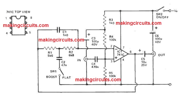
fig1 20

Along with SW1 open there is certainly practically 100% unfavorable feedback via R1, R2 and C1, providing the circuit unity gain and a flat result.

Pressing SW1 delivers C2 into circuit, and this decouples a few of the feedback by means of R1 and R2 at frequencies greater than a few hundred Hz providing the necessary increasing reaction.

Feedback via C1 at high treble frequencies leads to the step to drop away over around 5.5kHz, and inhibits the very higher frequency harmonics through getting extremely emphasized.

Because the unit has unity gain at frequencies where boost is not really used it may just be linked amongst the instrument as well as the amplifier

You'll also like:

  • 1.  Buzzer Circuit Using a Transistor and Piezo Element
  • 2.  Precision Guitar Tuner Circuit
  • 3.  Simplest Stereo Amplifier Circuit using IC LM380
  • 4.  Simple Microphone (MIC) Amplifier Circuits
  • 5.  Guitar Swell Pedal Circuit
  • 6.  Simple Electronic Bagpipe Music Generator Circuit

About Admin

Hey friends, Thanks a bunch for stopping by this site! I am an engineer with a Bachelor of Engineering in Electronics and Telecommunication. One of my passions is gathering information from all sorts of electronics books and tutorials. I then take that information and compile it into a language that is super easy to understand. My goal is to make those complex electronics circuit concepts and technical terms much more accessible for all the new and budding electronics engineers out there. I can also design customized circuit diagrams as required by the users.
If you have any questions related to this field, please do not hesitate to drop a comment! I am always here and ready to help you out with any queries you might have. I cannot wait to hear from you!

Reader Interactions

Comments

  1. Robert says

    July 28, 2022 at 5:49 pm

    where a gain pot be inserted in the circuit

    Reply
  2. Dale says

    August 23, 2021 at 2:52 pm

    I want it to peek at 4.3Khz, What is the R1, R2 , C1, C2 for that. Or what formula do you use?

    Reply
    • admin says

      September 1, 2021 at 11:06 am

      sorry don’t have the calculations with me right now…

      Reply

Leave a Reply Cancel reply

Your email address will not be published. Required fields are marked *

Primary Sidebar

Categories

  • 3 Phase (4)
  • 8051 Microcontroller (1)
  • Arduino (11)
  • Audio and Amplifier (102)
  • Automation (8)
  • Battery Chargers (64)
  • Bicycle Projects (4)
  • Car and Motorcycle Projects (39)
  • Datasheets (10)
  • DIY Projects (5)
  • Electrical (15)
  • Free Energy (6)
  • Games Projects (2)
  • High Voltage (14)
  • Hobby Projects (30)
  • Household Circuits (2)
  • IC 555 Circuits (5)
  • Ignition Circuits (2)
  • Indicators (50)
  • Infrared (6)
  • Inverter Circuits (29)
  • Lights and Lamps (97)
  • Medical (8)
  • Meter and Tester Circuits (38)
  • Motor Driver (17)
  • New Circuits (56)
  • Oscillators (30)
  • Pets and Pests (5)
  • Power supply (80)
  • Protection Circuits (25)
  • PWM (9)
  • Remote Control (20)
  • Security and Alarm Circuit (48)
  • Sensors and Detectors (66)
  • Signal Processor (23)
  • Solar Controller Circuits (62)
  • SSR (3)
  • Temperature Controller (20)
  • Timer (25)
  • Transformerless (7)
  • Transmitters (12)
  • Tutorials (45)
  • UPS (2)
  • Voltage Regulators (57)
  • Water Sensor and Controller (29)
  • Home
  • Privacy Policy
  • Contact
  • Disclaimer
  • Copyright

© 2025 · Making Easy Circuits