• Skip to main content
  • Skip to primary sidebar

Making Easy Circuits

Learn and build electronic circuits

You are here: Home / Power supply / Simple Variable Power Supply Circuit for Benchwork

Simple Variable Power Supply Circuit for Benchwork

Last Updated on January 10, 2018 by Admin 2 Comments

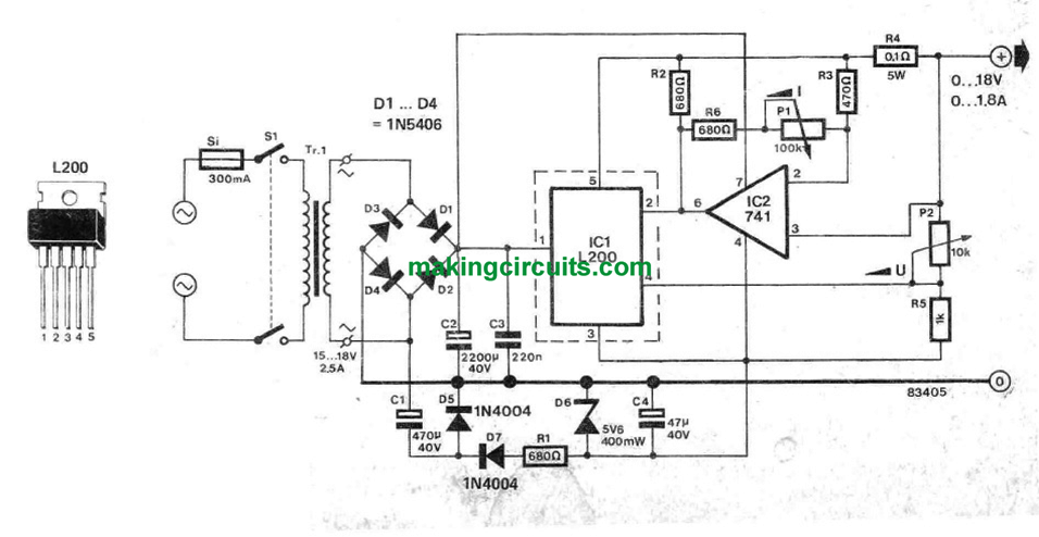
In case you assess the cost and the rating of this simple variable bench power supply you may receive a big surprise, as the output voltage and current tend to be totally variable between 0. . . 18 V and 0 . . . 1.8 A correspondingly and expenses have yet been maintained affordable. Referring to the circuit diagram: the input consists a 220V mains switch, fuse, transformer, bridge rectifier and a filter capacitor (C2).

Diode D5 and capacitor C1 create a negative supplementary voltage, that is stabilized through zener diode D6 and capacitor C4.

The negative voltage offers the negative supply for the two lCs. Pretty much everything is essential to help the output voltage to become fine-tuned lower to zero volts.

Throughout the development of this section of the circuit keep in mind that the positive terminal of electrolytic capacitor C4 is hooked up to ground! Control is given by lC1 and IC2. Capacitor C3 inhibits any kind of surplus transients at the input of IC1 and it also must for that reason be attached as strongly as you can to IC1 (similary C4 and lC2l.

The reference point output from pin 4 of IC1 would go to the voltage divider composed of R5 and P2 (this particular pot fixes the value of the output voltage). lC2 is actually linked like a differential amplifier and analyzes the signals at its two inputs.

The variation amongst the inputs may be the voltage drop throughout ‘current’ sensor R4. This specific lC feeds the current sensing input (pin 2) of the L200.

P1 within the feedback hook of the 741 is employed to change the output current in the circuit. IC1 has to be attached to an appropriate heat sink because it emits almost all the power of the circuit.

This simple variable bench power supply circuit may without difficulty be constructed into a box along with a voltmeter and ammeter attached to the front board. Because of the precision of the circuit all these must essentially be electronic meters, however almost any sort will work.

simple variable bench power supply circuit

You'll also like:

  • 1.  4.5 V, 6 V, 9 V , 12 V Power Supply Circuit
  • 2.  Surge free Transformerless Power Supply Circuit using zero Crossing Detection
  • 3.  Build this One Transistor Regulated Power Supply Circuit
  • 4.  Simple Short-Circuit Protection for Power Supplies
  • 5.  Adjustable Current Switch Mode Power Supply (SMPS) Circuit
  • 6.  +/- 15V Dual Regulated Power Supply Circuit

About Admin

Hey friends, Thanks a bunch for stopping by this site! I am an engineer with a Bachelor of Engineering in Electronics and Telecommunication. One of my passions is gathering information from all sorts of electronics books and tutorials. I then take that information and compile it into a language that is super easy to understand. My goal is to make those complex electronics circuit concepts and technical terms much more accessible for all the new and budding electronics engineers out there. I can also design customized circuit diagrams as required by the users.
If you have any questions related to this field, please do not hesitate to drop a comment! I am always here and ready to help you out with any queries you might have. I cannot wait to hear from you!

Reader Interactions

Comments

  1. Feri says

    November 8, 2021 at 7:21 am

    missing elec. capacitor betwen D7 R1 and ground.

    Reply
    • admin says

      November 15, 2021 at 9:46 am

      I don’t think it is required

      Reply

Leave a Reply Cancel reply

Your email address will not be published. Required fields are marked *

Primary Sidebar

Categories

  • 3 Phase (4)
  • 8051 Microcontroller (1)
  • Arduino (11)
  • Audio and Amplifier (102)
  • Automation (8)
  • Battery Chargers (64)
  • Bicycle Projects (4)
  • Car and Motorcycle Projects (39)
  • Datasheets (10)
  • DIY Projects (5)
  • Electrical (15)
  • Free Energy (6)
  • Games Projects (2)
  • High Voltage (14)
  • Hobby Projects (30)
  • Household Circuits (2)
  • IC 555 Circuits (5)
  • Ignition Circuits (2)
  • Indicators (50)
  • Infrared (6)
  • Inverter Circuits (29)
  • Lights and Lamps (97)
  • Medical (8)
  • Meter and Tester Circuits (38)
  • Motor Driver (17)
  • New Circuits (56)
  • Oscillators (30)
  • Pets and Pests (5)
  • Power supply (80)
  • Protection Circuits (25)
  • PWM (9)
  • Remote Control (20)
  • Security and Alarm Circuit (48)
  • Sensors and Detectors (66)
  • Signal Processor (23)
  • Solar Controller Circuits (62)
  • SSR (3)
  • Temperature Controller (20)
  • Timer (25)
  • Transformerless (7)
  • Transmitters (12)
  • Tutorials (45)
  • UPS (2)
  • Voltage Regulators (57)
  • Water Sensor and Controller (29)
  • Home
  • Privacy Policy
  • Contact
  • Disclaimer
  • Copyright

© 2025 · Making Easy Circuits