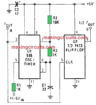
The circuit as shown in Figure below presents a 555 as an extremely simple, voltage-controlled oscillator (VCO). The VCO’s output frequency (U1) differs contrariwise with the input voltage. Using a 1 V input, the oscillator’s output frequency is around 1500 Hz. If you supply a 5-V input, the oscillator’s output frequency dips to about 300 Hz.
This means the output frequency range of U1 can be modified by fluctuating the values of C1, R2 and R3. If you increase the value of any one of these devices, the oscillator frequency will be reduced. Alternately, if you decrease either the capacitance or resistance, the frequency will be increased.

As a result, the output-waveform symmetry gets affected as the frequency fluctuates from one end to the other. At the peak frequency, the waveform is shared. However, as the frequency dips the output of the circuit switches into a thin pulse.
Say you need a symmetrical waveform, you just need to introduce a second IC, U2 (half of a 7473P dual TTL J-K flip-flop) to the oscillator circuit. But there’s a catch. U2’s signal frequency output is one-half of what is entering. To compensate the discrepancy, you just need to two-fold the frequency of the voltage controlled oscillator (VCO).
Simple VCO using LM3900
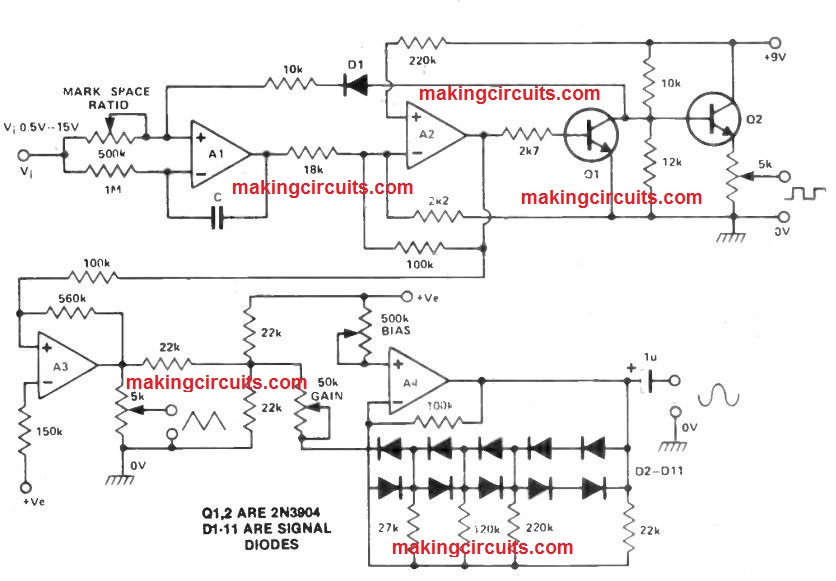
Through the use of the LM 3900N quad opamp, an easy convenient battery controlled VCO could be built quite at low cost.
A1 forms an integrator, the ramp rate based on the voltage Vi and capacitor C. This ramp is fed to a Schmidt trigger which switches at around 5V8, creating A1 ramp down, producing a triangular wave of around OV85.

The Schmidt trigger supplies a transistor switch and an emitter follower.
The triangular wave is then fed to A3 which will act as an inverting amplifier, and the output is fed to A4 which can be an hugh integrator set at a pseudo ground of 4V5.
The bias and gain pots of the voltage controlled oscillator circuit needs to be modified to achieve the ideal sine waveform. Vi could be any kind of positive voltage from +0.5 to + 15.0 V, providing an frequency range of around 1:100.
Capacitor C could be any value from 1 On to 47n and the outputs possess a low distortion around about 20 kHz.
Leave a Reply