• Skip to main content
  • Skip to primary sidebar

Making Easy Circuits

Learn and build electronic circuits

You are here: Home / Signal Processor / Simple Voltage Controlled Oscillator using IC 555

Simple Voltage Controlled Oscillator using IC 555

Last Updated on January 10, 2018 by Admin 2 Comments

A neat little voltage controlled oscillator circuit could be designed and applied for a given purpose using a single IC 555 and a few other passive components, let's learn about this simple yet useful circuit from the following discussion.

How the Circuit Works


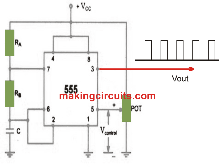
A voltage controlled oscillator (VCO) employing timer 555 is demonstrated in the following diagram.

controlled

The circuit is oftentimes known as voltage-to-frequency converter, considering that the output frequency could be transformed by changing the input voltage.

As expressed in earlier content, terminal pin 5 is the voltage control terminal and its particular functionality is to control the threshold and the trigger level. Generally, the control voltage is + 2/3 V DC, due to the internal voltage divider.

Even so, an external voltage could be placed on this terminal directly or by way of a pot, as highlighted in the figure, through altering the pot, the control voltage could be varied.

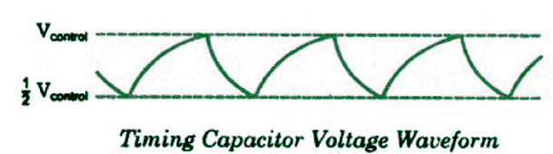
Voltage over the timing capacitor is displayed in the figure, that can vary between + V control and ½ V control. When the control voltage is elevated, the capacitor requires a lengthier time to charge and discharge, the frequency, consequently, diminishes. Therefore, the frequency could be improved by changing the control voltage linearly.


Waveform Generated across the IC 555 pinouts

It would be also interesting to learn what kind of waveform are initiated across the various pinouts of the IC 555.

When a varying voltage is applied at the control input of the IC, the amplitude of the triangle waves across the timing capacitor or between the pin#6/2 and the ground also proportionately varies. Higher voltages at pin#5 causes higher amplitude on the triangle waves and vice versa

triangle

However the pin#3 of the IC produces an entirely different response for this voltage controlled oscillator circuit. The pin#3 generates a PWM waveform whose duty cycle varies exactly in proportion with the level of voltage applied at pin#5 of the IC.

You'll also like:

  • 1.  Making an Electronic Tuning Fork Circuit
  • 2.  Exponential Waveform Generator Circuit
  • 3.  Dog Barking Sound Simulator Circuit
  • 4.  5 Band Graphic Equalizer Circuit
  • 5.  How to Build a RF Signal Jammer Circuit
  • 6.  Very Low Frequency (VLF) Converter Circuit

About Admin

Hey friends, Thanks a bunch for stopping by this site! I am an engineer with a Bachelor of Engineering in Electronics and Telecommunication. One of my passions is gathering information from all sorts of electronics books and tutorials. I then take that information and compile it into a language that is super easy to understand. My goal is to make those complex electronics circuit concepts and technical terms much more accessible for all the new and budding electronics engineers out there. I can also design customized circuit diagrams as required by the users.
If you have any questions related to this field, please do not hesitate to drop a comment! I am always here and ready to help you out with any queries you might have. I cannot wait to hear from you!

Reader Interactions

Comments

  1. Shambavi says

    June 5, 2019 at 9:23 pm

    How to design sinusoidal VCO using 555 times ic

    Reply
    • admin says

      June 19, 2019 at 9:18 am

      By using a push-pull BJT stage at pin#3 of the IC

      Reply

Leave a Reply Cancel reply

Your email address will not be published. Required fields are marked *

Primary Sidebar

Categories

  • 3 Phase (4)
  • 8051 Microcontroller (1)
  • Arduino (11)
  • Audio and Amplifier (102)
  • Automation (8)
  • Battery Chargers (64)
  • Bicycle Projects (4)
  • Car and Motorcycle Projects (39)
  • Datasheets (10)
  • DIY Projects (5)
  • Electrical (15)
  • Free Energy (6)
  • Games Projects (2)
  • High Voltage (14)
  • Hobby Projects (30)
  • Household Circuits (2)
  • IC 555 Circuits (5)
  • Ignition Circuits (2)
  • Indicators (50)
  • Infrared (6)
  • Inverter Circuits (29)
  • Lights and Lamps (97)
  • Medical (8)
  • Meter and Tester Circuits (38)
  • Motor Driver (17)
  • New Circuits (56)
  • Oscillators (30)
  • Pets and Pests (5)
  • Power supply (80)
  • Protection Circuits (25)
  • PWM (9)
  • Remote Control (20)
  • Security and Alarm Circuit (48)
  • Sensors and Detectors (66)
  • Signal Processor (23)
  • Solar Controller Circuits (62)
  • SSR (3)
  • Temperature Controller (20)
  • Timer (25)
  • Transformerless (7)
  • Transmitters (12)
  • Tutorials (45)
  • UPS (2)
  • Voltage Regulators (57)
  • Water Sensor and Controller (29)
  • Home
  • Privacy Policy
  • Contact
  • Disclaimer
  • Copyright

© 2025 · Making Easy Circuits