As far as I know this may be the easiest and high quality FM radio circuit that could be built by any new hobbyist. In addition, this circuit's FM reception quality is pretty impressive, although the level of sensitivity may not be that good.
The theory of this receiver may seem a little bit unconventional to many. It is according to a 'synchronizable oscillator' made up of transistors T2 and T3 which is synchronized to the captured FM stations through T1.
This transistor works as a wide band HF preamplifier for the FM band.
Actually, this amplification stage could possibly be removed and the antenna hooked up straight to capacitor C4, though the sensitivity would likely then be significantly lowered.
The oscillator is tuned by capacitor C5 to approximately 87 ... 108 MHz and, as a result of synchronization mentioned previously, the frequency exhibits exactly the same oscillations as the transmission captured by the antenna.
These frequency oscillations, obviously, signify the AF data.
The AF data is acquired by the basic reason of looking at the T2/T3 oscillator as an upside down transmitter then a tiny modulating voltage across P1/R5 could be ample to bring about the frequency modulation.
The opposite of this is that if the transmission is previously frequency modulated through an alternate method this will result in a modulated voltage to be created around P1/R5.
This voltage signifies the primary data sent. Therefore following low-pass filtering R6/C6 and amplification (T4 to T6) the demodulated AF transmission is introduced on the circuit.
The winding specifications for the various coils are furnished below the circuit diagram. The radio is tuned to different stations by means of tuning capacitor C5. Potentiometer P1 should subsequently be adjusted to allow the ideal FM reception of the transmitter.
When integrated with a loudspeaker and an amplifier (for example an LM386 amplifier), this simple FM radio circuit could very easily be constructed into a extremely sleek and stylish pocket radio.
Circuit Diagram
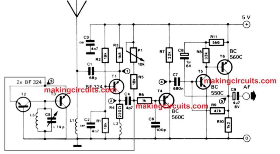
Test Point Voltages
- 3.4 V
- 0.2 V
- 0.66 V
- 1.2 V
- 0.73 V
Coil Specifications
L1 = 10 turns CuL, ⌀ 0.5 mm (SWG 25), d = 3 mm
L2 = 13 turns CuL, ⌀ 0.5 mm (SWG 25), d = 5 mm
L3 = 10 turns CuL, ⌀ 1.2 mm (SWG 25), d = 5 mm
Hello, is it possible to replace the variable capacitor with a varactor,if so how? Im not very skilled at FM/AM transmissions. Its very hard to get any variable caps for reasonable price here, and i cant wait for the order to come.
Sorry, that’s not recommended. C5 is a standard trimmer, you can easily procure any trimmer rated at around 33 pF.
yes ! you can add a varactor diode
Is there any possible way to make a small additional circuit that can receive AM? I would add a spdt switch to the base of T5 transistor to change between am and fm. Is it possible to modify the circuit to improve a sensivity somehow and add AM receiving? pls help
I do not have an AM receiver circuit so not sure how to solve your problem….
ok, and one question. all voltages are good, but measuring point number 5 shuld have 0,73V and I have almost 5V. what could be the reason?
I understand the problem, but I can’t figure out why the voltages are not matching?
Pz check R9 (47k),I think you may have put 4.7k there because this NPN Tr will be hard on doing the same to PNP Tr BC560 which should result in close to 5v there as mentioned there by you.
Hello, i have measured everything and this point is the only one not matching. I also checked the resistor as mentioned above and its correct, do you have any idea what could otherwise be the reason?
Hello, i think i may have found out the issue with test point 5 having 5v, when anything flows into the NPN tr, the full 5v will show up on test point 5. I tried changing the PNP to NPN and now i have the correct voltage, i dont know if the rest of the circuit is affected but the voltage checks now.
Thank you for the feedback.
Please check, L3 is swg 18 not 25 according to diameter indicated.
yes you are right, but according to me the thickness does not matter much, since these are all low current coils
is T3 a BF324 ?
yes that’s right!