• Skip to main content
  • Skip to primary sidebar

Making Easy Circuits

Learn and build electronic circuits

You are here: Home / Power supply / Simplest Variable 0-100V Power Supply Circuit

Simplest Variable 0-100V Power Supply Circuit

Last Updated on May 23, 2018 by Admin 14 Comments

This simplest variable 0-100V power supply circuit will allow the user to get a seamlessly adjustable output voltage, which could e fixed at any desired level. The power supply ca handle as high as 10 amps which looks adequate for most electronic circuit requirement.

A straightforward yet an effective technique of controlling a DC voltage can be to employ a voltage divider and transistor emitter follower arrangement. The image down the page shows applying a 1K pot to create the base voltage of any suitable power NPN transistor.

The collector of the NPN operates the base of a more substantial PNP power transistor that resources the required amount of current to the connected load.

The output voltage is going to be around 0.7 volts under the voltage at the slider arm of the 1K pot therefore the output can easily become variable from 0 to the full supply voltage (100V) subtracting 0.7 volts.

Applying a couple of transistors offers a good current gain of approximately 1000 or maybe more to ensure that solely a few milliamps of current is actually consumed through the voltage divider to provide a few amps of current at the output.

Remember that this circuit is not too efficient compared to a switch mode type of power supply, or using a variable duty cycle switching technique. Within the figure below, the load could work with about 10 amps at 12 volts and at 3 amp at 3.6 volts.

A relatively substantial heat sink may be necessary in order to avoid the PNP power transistor getting too hot. The energy drawn by the load could be just (3 volts * 1 amp) = 3 watts which usually offers us an efficiency aspect of not more than 50% while the load voltage is reduced.

The benefit of the circuit is ease-of-use, as well as this it will not produce any kind of RF disturbance compared to a switching regulator. This simple variable 0-100V power supply circuit works extremely well as a voltage regulator in case the input voltage stays consistent, however it is not going to make up for adjustments within the input like the LM317 counterpart does.

Variable 0-100V Power Supply Circuit


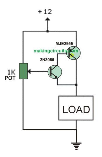
Note: The diagram shows the circuit operating with a 12V input, but the supply could be 100V maximum, for getting the expected 0-100V variable output, however make sure to upgrade the pot to 10K in such circumstances.

You'll also like:

  • 1.  How to Calculate Ferrite Transformer for SMPS
  • 2.  Surge free Transformerless Power Supply Circuit using zero Crossing Detection
  • 3.  Simple Adjustable Constant Current Circuit
  • 4.  High End Bench Power Supply with Variable Voltage/Current
  • 5.  Make these Low Dropout Regulator Circuits at Home
  • 6.  Adjustable Power Supply 3 to 30V 3A Circuit

About Admin

Hey friends, Thanks a bunch for stopping by this site! I am an engineer with a Bachelor of Engineering in Electronics and Telecommunication. One of my passions is gathering information from all sorts of electronics books and tutorials. I then take that information and compile it into a language that is super easy to understand. My goal is to make those complex electronics circuit concepts and technical terms much more accessible for all the new and budding electronics engineers out there. I can also design customized circuit diagrams as required by the users.
If you have any questions related to this field, please do not hesitate to drop a comment! I am always here and ready to help you out with any queries you might have. I cannot wait to hear from you!

Reader Interactions

Comments

  1. avelia says

    June 15, 2022 at 10:37 am

    instead of the two transistors could not use a darlington
    transistor thank you for your answer if yes which one could be suitable

    Reply
    • admin says

      June 19, 2022 at 11:00 am

      Yes a single Darlington can be used

      Reply
  2. Imsa Naga says

    December 22, 2021 at 7:01 pm

    Can MJE2955 handle 100V ? (for 0-100V PSU)

    Reply
    • admin says

      December 28, 2021 at 10:13 am

      No it cannot handle 100V, maximum is 60 V

      Reply
      • arun says

        October 14, 2022 at 4:33 pm

        so you mean this two transistor can handle 100 V – 3 amps ?

        Reply
        • admin says

          October 16, 2022 at 6:43 pm

          Please check the datasheet of the transistor to know exactly know how much maximum voltage it can handle.

          Reply
  3. Adesoji ADEREMI says

    November 15, 2020 at 11:17 am

    Can I use 2 PNP transistors for current amplification?

    Reply
    • admin says

      November 16, 2020 at 8:52 pm

      yes you can….

      Reply
  4. Adesoji ADEREMI says

    November 15, 2020 at 12:00 am

    Can you add more 2n3055 transistors for more current like 30 amps at 40 volts?

    Reply
    • admin says

      November 16, 2020 at 8:52 pm

      Yes That’s definitely possible

      Reply
      • Ray says

        April 15, 2023 at 12:15 pm

        Wouldn’t turning that 1k pot to 0 short the 12V to Ground?

        Reply
        • admin says

          April 19, 2023 at 9:23 am

          The base of the NPN could be subjected to direct 12V, so a base resistors should be added.

          Reply
  5. spencer says

    May 22, 2018 at 6:02 pm

    your MJE2955 transistor is “upside-down”…

    Reply
    • admin says

      May 23, 2018 at 9:06 pm

      thank for pointing it out, will correct it soon.

      Reply

Leave a Reply Cancel reply

Your email address will not be published. Required fields are marked *

Primary Sidebar

Categories

  • 3 Phase (4)
  • 8051 Microcontroller (1)
  • Arduino (11)
  • Audio and Amplifier (102)
  • Automation (8)
  • Battery Chargers (64)
  • Bicycle Projects (4)
  • Car and Motorcycle Projects (39)
  • Datasheets (10)
  • DIY Projects (5)
  • Electrical (15)
  • Free Energy (6)
  • Games Projects (2)
  • High Voltage (14)
  • Hobby Projects (30)
  • Household Circuits (2)
  • IC 555 Circuits (4)
  • Ignition Circuits (2)
  • Indicators (50)
  • Infrared (6)
  • Inverter Circuits (29)
  • Lights and Lamps (97)
  • Medical (8)
  • Meter and Tester Circuits (38)
  • Motor Driver (17)
  • New Circuits (56)
  • Oscillators (30)
  • Pets and Pests (5)
  • Power supply (81)
  • Protection Circuits (25)
  • PWM (8)
  • Remote Control (20)
  • Security and Alarm Circuit (48)
  • Sensors and Detectors (66)
  • Signal Processor (23)
  • Solar Controller Circuits (61)
  • SSR (3)
  • Temperature Controller (20)
  • Timer (25)
  • Transformerless (7)
  • Transmitters (12)
  • Tutorials (45)
  • UPS (2)
  • Voltage Regulators (57)
  • Water Sensor and Controller (29)
  • Home
  • Privacy Policy
  • Contact
  • Disclaimer
  • Copyright

© 2025 · Making Easy Circuits