• Skip to main content
  • Skip to primary sidebar

Making Easy Circuits

Learn and build electronic circuits

You are here: Home / Inverter Circuits / Make this Sine Wave Inverter Circuit using Bubba Oscillator

Make this Sine Wave Inverter Circuit using Bubba Oscillator

Last Updated on January 5, 2025 by Admin Leave a Comment

This tutorial explains how to use a Bubba oscillator sine wave generator to create a basic sine wave inverter. A devoted reader of my site asked for the suggestion.

Fundamental Details

I'm an electrical engineering B.Tech student in my fourth year.

For the end of the semester, we are attempting to create a pure wave sine wave inverter utilizing PWM and a Bubba oscillator; additionally, a battery charging and auto cutoff circuit might be required.

Considering daily needs, we require the inverter to function. If you could provide a functional circuit for this, i would surely be very appreciative.

Many thanks!

Circuit Diagram

bubba2Binverter

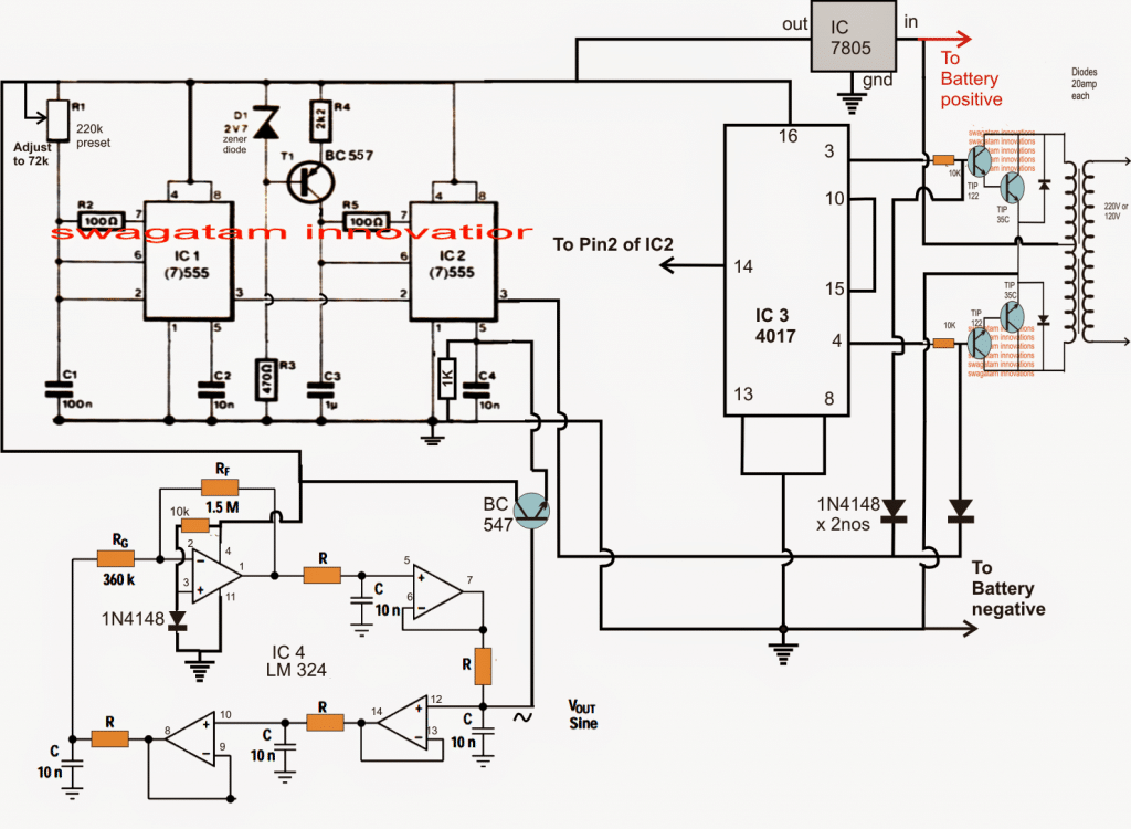
NOTE: For effective PWM transformation, consider a Darlingtton pair to power the BC547 connected to pin #5 of IC2.

The Circuit Layout

Below details will help you understand the suggested sine wave inverter utilizing a bubba oscillator: 

With regard to the modulation input supplied at its pin 5, IC1 creates a square pulse generator for the PWMs, whereas IC2 creates a monostable PWM generator. The stage is made up of two 555 ICs that are set as PWM generators.

A bubba oscillator made with four opamps from the IC LM324 is used to achieve the sine wave modulation input at pin 5 of IC2.

The produced sine wave pulses are supplied to pin 5 of IC2 via a BJT common collector for additional analysis after being precisely set at 50 Hz.

The Basic Formula for 50 Hz

Using a particular formula, R has been accurately chosen for establishing the bubba oscillator's frequency at 50 Hz:

f = 1/2(3.14)RC

IC2 creates an analogous PWM waveform at pin 3 after comparing the square pulses at pin 2 with the sine wave modulations at pin 5.

Only one IC 4017, the outputs of which were suitably integrated with the two high gain, high current power BJT stages generated by Darlington TIP122 and TIP35, is used to setup the flip flop stage needed for power stage switching.

To accomplish a 50 HZ switching between the power transistors, pin 3 of IC1 is used to clock pin 14 of the 4017 at about 200 Hz.

Two 1N4148 diodes interconnected between the bases of the tIP122 are used to accomplish the PWM modulation of the aforementioned 50 Hz switching. These diodes are switched to correspond with the PWM from pin 3 of IC1.

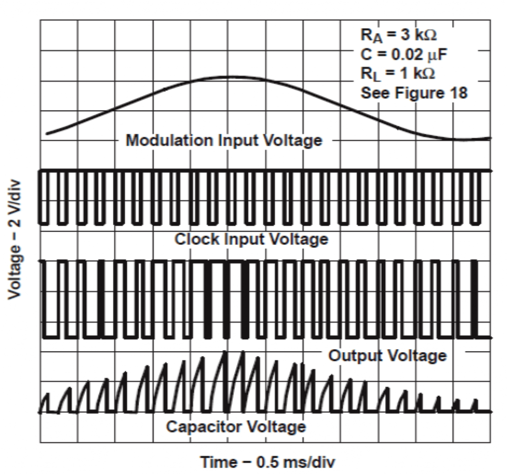
The diagram that follows could be used to relate to the anticipated waveforms of the PWMs:

Bubba oscillator waveform

555 pwm waveforms 1024x956 1

You'll also like:

  • 1.  Simple 2000 Watts Power Inverter Circuit
  • 2.  Quartz Mosquito Repellent using a single IC4060
  • 3.  Simple Sawtooth Generator Circuit
  • 4.  1 MHz Time Base Generator Circuit
  • 5.  No Load Detection Shut Down for Inverters
  • 6.  Motor Boat Sound Generator Circuit

About Admin

Hey friends, Thanks a bunch for stopping by this site! I am an engineer with a Bachelor of Engineering in Electronics and Telecommunication. One of my passions is gathering information from all sorts of electronics books and tutorials. I then take that information and compile it into a language that is super easy to understand. My goal is to make those complex electronics circuit concepts and technical terms much more accessible for all the new and budding electronics engineers out there. I can also design customized circuit diagrams as required by the users.
If you have any questions related to this field, please do not hesitate to drop a comment! I am always here and ready to help you out with any queries you might have. I cannot wait to hear from you!

Reader Interactions

Leave a Reply Cancel reply

Your email address will not be published. Required fields are marked *

Primary Sidebar

Categories

  • 3 Phase (4)
  • 8051 Microcontroller (1)
  • Arduino (11)
  • Audio and Amplifier (102)
  • Automation (8)
  • Battery Chargers (64)
  • Bicycle Projects (4)
  • Car and Motorcycle Projects (39)
  • Datasheets (10)
  • DIY Projects (5)
  • Electrical (15)
  • Free Energy (6)
  • Games Projects (2)
  • High Voltage (14)
  • Hobby Projects (30)
  • Household Circuits (2)
  • IC 555 Circuits (4)
  • Ignition Circuits (2)
  • Indicators (50)
  • Infrared (6)
  • Inverter Circuits (29)
  • Lights and Lamps (97)
  • Medical (8)
  • Meter and Tester Circuits (38)
  • Motor Driver (17)
  • New Circuits (56)
  • Oscillators (30)
  • Pets and Pests (5)
  • Power supply (81)
  • Protection Circuits (25)
  • PWM (8)
  • Remote Control (20)
  • Security and Alarm Circuit (48)
  • Sensors and Detectors (66)
  • Signal Processor (23)
  • Solar Controller Circuits (61)
  • SSR (3)
  • Temperature Controller (20)
  • Timer (25)
  • Transformerless (7)
  • Transmitters (12)
  • Tutorials (45)
  • UPS (2)
  • Voltage Regulators (57)
  • Water Sensor and Controller (29)
  • Home
  • Privacy Policy
  • Contact
  • Disclaimer
  • Copyright

© 2025 · Making Easy Circuits