• Skip to main content
  • Skip to primary sidebar

Making Easy Circuits

Learn and build electronic circuits

You are here: Home / UPS / Sinewave UPS Circuit using PIC16F84A

Sinewave UPS Circuit using PIC16F84A

Last Updated on January 10, 2018 by Admin Leave a Comment

The sinewave UPS circuit using PIC16F 84A microcontroller IC is cheap, versatile and can be a perfectly small UPS which can be used in homes, offices, shops to get a ready 24x7 power whenever the AC power fails.

The circuit design is not complex and comprises all the necessary stage which a standard UPS ought to possess. To be precise the circuit includes a center tap transformer based inverter circuit, a fully automatic battery charger circuit with over charge and low charge cut off, an output overload protection and over voltage protection stage, a buzzer beeper stage when the UPS is running in the inverter mode, and most importantly it includes a rapid relay changeover stage which makes sure that the transition from mains to inverter or vice versa is triggered with least delay and as quickly as possible, this is to ensure that any critical load associated with the UPS is not affected by a short transition lapse, rather switched with a uninterrupted accuracy.

PIC sinewave UPS circuit

The main stages of the circuit can be understood from the following points:

A PIC16F84A microcontroller stage primarily monitors the frequency generation for the inverter stage. It not only generates the basic 50Hz with utmost accuracy, the microcontroller also becomes responsible for driving power transistors with a pure sinewave frequency (SPWM) ensuring a perfectly optimized sine waveform at the output of the transformer. It also handles the buzzer triggering in the form of intermittent beeps whenever an AC mains failure is detected.

The other features are monitored the external opamps which execute the required battery charing and other related protection features of the UPS circuit.

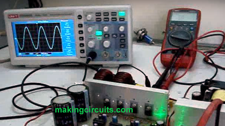
The inverter section is built using a basic push pull center tap transformer circuit which is switched alternately using power BJTs to keep things simple and manageable. Mosfets are avoided since mosfets require much stringent PCB designing parameters.

pic16f84a-sinewave-INVERTER

The HEX codes and the other crucial information for this sinewave UPS circuit using PIC16F84A MCU can be downloaded from the above link:


You'll also like:

  • 1.  How To Make a 6V to 220V Boost UPS Circuit for Satellite TV Modems

About Admin

Hey friends, Thanks a bunch for stopping by this site! I am an engineer with a Bachelor of Engineering in Electronics and Telecommunication. One of my passions is gathering information from all sorts of electronics books and tutorials. I then take that information and compile it into a language that is super easy to understand. My goal is to make those complex electronics circuit concepts and technical terms much more accessible for all the new and budding electronics engineers out there. I can also design customized circuit diagrams as required by the users.
If you have any questions related to this field, please do not hesitate to drop a comment! I am always here and ready to help you out with any queries you might have. I cannot wait to hear from you!

Reader Interactions

Leave a Reply Cancel reply

Your email address will not be published. Required fields are marked *

Primary Sidebar

Categories

  • 3 Phase (4)
  • 8051 Microcontroller (1)
  • Arduino (11)
  • Audio and Amplifier (102)
  • Automation (8)
  • Battery Chargers (64)
  • Bicycle Projects (4)
  • Car and Motorcycle Projects (39)
  • Datasheets (10)
  • DIY Projects (5)
  • Electrical (15)
  • Free Energy (6)
  • Games Projects (2)
  • High Voltage (14)
  • Hobby Projects (30)
  • Household Circuits (2)
  • IC 555 Circuits (4)
  • Ignition Circuits (2)
  • Indicators (50)
  • Infrared (6)
  • Inverter Circuits (29)
  • Lights and Lamps (97)
  • Medical (8)
  • Meter and Tester Circuits (38)
  • Motor Driver (17)
  • New Circuits (56)
  • Oscillators (30)
  • Pets and Pests (5)
  • Power supply (81)
  • Protection Circuits (25)
  • PWM (8)
  • Remote Control (20)
  • Security and Alarm Circuit (48)
  • Sensors and Detectors (66)
  • Signal Processor (23)
  • Solar Controller Circuits (61)
  • SSR (3)
  • Temperature Controller (20)
  • Timer (25)
  • Transformerless (7)
  • Transmitters (12)
  • Tutorials (45)
  • UPS (2)
  • Voltage Regulators (57)
  • Water Sensor and Controller (29)
  • Home
  • Privacy Policy
  • Contact
  • Disclaimer
  • Copyright

© 2025 · Making Easy Circuits