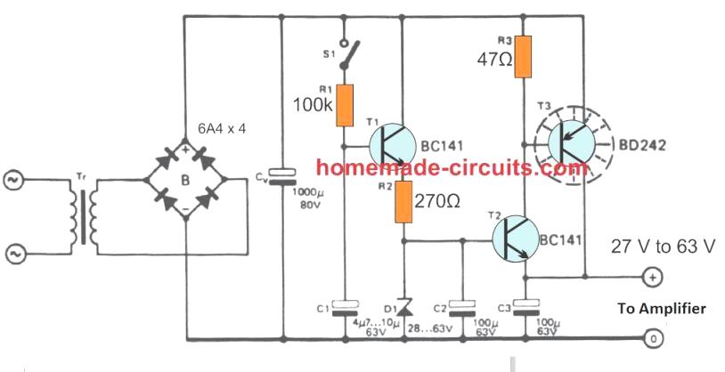
The purpose of the suggested slow-start power supply circuit is to prevent the loudspeaker which is hooked up to the amplifier from producing an unpleasant and loud "thump" sound when the power switch is turned on.
Additionally, it means that the power supply will shield the loudspeakers from the power source's abrupt surge current spike and guarantee their extended lifespan.
The associated amplifier and its speakers may be used securely with this power source, negating the demand for additional safeguards like fuses or delay ON circuits.
Transient Power Switch-ON
The majority of amplifier concepts, regardless they are commercially manufactured or do-it-yourself, have the drawback of producing a loud "thump" sound whenever the power switch is turned on. This is typically caused by the output filter electrolytic capacitors charging excessively quickly, resulting in it impossible to halt the first abrupt switch ON transient.
It is believed that there could be a significant chance that loudspeakers might short out and fire at any given moment assuming this issue occurs in a high-power amplifier circuit.
A gradually rising voltage power supply circuit, that is covered in the following section, is an alternative concept for improving the erratic amplifier. It is just a simple transistorized regulator with a soft start or slow start capability added.
The Circuit's Operation
Following is the full circuit schematic for the power supply for the slowly operating soft start amplifier:

The smoothing capacitor CO and rectifier B provide the initial crude supply. Given that the output voltage is smaller, at about 600 mV, zener diode D1 provides the reference voltage. If necessary, a few series-connected zener diodes might be used to create the desired voltage.
One might choose a maximum zener voltage of roughly 28 V to 63 V. Switch S1, which is attached to the mains AC switch, turns the supply on and off. As soon as it is closed or switched on, the voltage across C1 increases to its functioning limit in about one second.
Up to the point when the zener diode turns into conductive, also known as the activation cutoff of the zener, the output voltage starts to increase in tandem with the growing voltage across C1.
The leakage via the base current input for the transistor T1 causes the C1 voltage to start decreasing in around five seconds whether S1 remains open or not shut. It could be feasible to completely remove the switch S1 and associate the S1 terminals with a wire link if the amplifier shows no noticeable switch-off voltage spikes, meaning that no special turn-off method is required.
At C1, the unregulated voltage cannot exceed 80 V. It needs to be chosen to guarantee that there is enough voltage drop across T3 to handle the regulation specifications.
A drop that is excessively high would result in a waste of electricity and perhaps need an expensive heat sink that is not needed.
The fundamental idea is that the ripple waveform must demonstrate around 2 volts over the series transistors on the troughs when the supply input has been fully loaded and the incoming mains AC voltage is at its lowest (expected) range.
As a substitute, it could be reasonable to assume that T3 will continuously require a small heat sink (such as a 2 mm thick, glossy metal object that is around 10 cm by 10 cm) and to accommodate approximately ten volts over T3 (in the absence of additional load).
Enhancing T2 with ventilation fins or expansions may also be necessary in extreme circumstances.
The 1000 µF capacitor value that is shown for CV is only an estimate.
The formula Q = CV may be used to simply compute the fundamental transformer/bridge supply, which additionally connects to a suitable optimal load, if you're interested in doing so. Remember in mind that each rectifier creates 100 ripples per second.
Leave a Reply