The article talks about a surprisingly simple under soil gold detector circuit for estimating buried metals like gold, iron, tin, brass etc by detecting alternation in the resistance of the specific earth deposits.
Larger physiological matter which can be hidden within the topsoil could possibly be discovered by means of a alteration in the electrical resistance of the earth surface at different depths. The layout is related to a system that can be used for implementing appropriate alterations on the resistance of the soil. This specific program may be also helpful in archaeological excavations.
Deep Soil Gold Detector Circuit - Ground Scanner
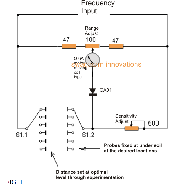
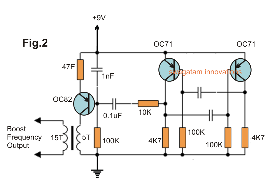
The suggested deep soil gold detector device consists of the measuring bridge (figure 1), the alternating voltage generator (fig 2) and the a few probes, sunken inside the earth.
The resistances across the soil deposits, between the electrodes of probes are paired to the input of the bridge arms, for calibrating the variables.
Before detection of gold the 100 ohm resistor may very well be realigned for bridging the balance to ensure that the dial instrument readings are originally at the zero level.
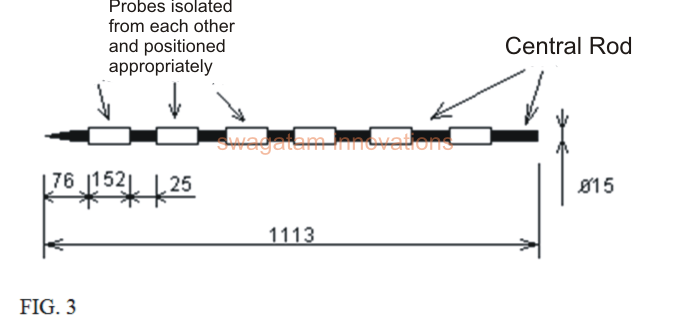
The model of the probe symbolized in FIG.3 may e recognized as follows:
Each one of the probes represents the insulated rods possessing a diameter of around 1.5 mm. from the outside section of the bar along its axle, these are generally stationary electrodes available as six thin-walled tube, segregated from each other.
Each one electrode probe with the assistance of six cable connectivity is installed on the switch S1 measuring bridge, that subsequently hooks up with one of the 6 pairs of electrodes along with the bridge.
Within this illustration, each one pair of electrodes at each of the placements of the switch S1 symbolize the accurate detail of the soil layer and its content.
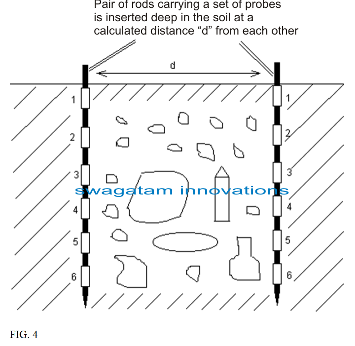
Immediately after positioning the probe in the field, as outlined by FIG. 4, the electrical resistance of the succeeding layers of soil introduced at various depths is identified.
Assessing the values attained from the resistance, it is possible to get a realization at exactly what depth (which soil layer) are objects like gold that may be influencing the resistance of the soil.
The distance between the probes are basically selected in each specific scenario. Sometimes, attaining your goal might be fulfilled with range that me around close to 2.4 m.
The variable resistor of the bridge is 500 ohms as demonstrated in the deep soil gold detector circuit diagram, is for optimizing the sensitivity of the bridge based on soil type being researched.
OC 71 transistors, wow they are older than god…
You can try any other equivalent Germanium transistor.
Hello i’m Sarathi Tech lead in my company. actually we planned to built a drone with metal detector, according to your study how much distance we can detect the metals buried on earth. how we can increase the detecting range. please reply for my query it will helpful for my R&D.
Hi, there is sensitivity adjustment pot which can used to increase the range of the circuit.
the circuitry is incomplete and also the information or details, how depth the gold should be detected,the probes how many will be used and spacing of probes.
My name is Lackson Kasekwa.I live in Tanzania where there Gold.Please may you send me a good Gold detector Machine so that we can do business i send you money.I can work on it i get money or to sell them.I am honor so that i can do.My phone +255 754446059
Sorry Lackson, we don’t build and sell kits.
what is depth of this coil
Kya ye wakai kaam karta hai.?
Parts list.
Please ??
sorry, test nahi kiya ab tak…maloom nahi