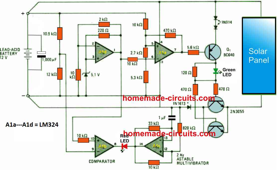
This single IC LM324 based verified efficient regulator circuit provides an energy-saving solution for charging lead-acid batteries, which are often found in motor vehicles, for all solar panel systems.
The cost of the solar regulator is hardly $5, without including the cost of the solar cells, which are presumably in front of you for use in a number of alternative ideas.

This circuit disconnects the charging source from the battery, doing away with the requirement for large shunt resistors, in contrast to a variety of other shunt regulators that, after the battery is fully charged, would divert current through a resistor.
Circuit Description
Transistors Q1, Q2, and Q3 turn on when the battery voltage falls below 13.5 volts, which is typically the open-circuit voltage of a 12 V battery. At that point, the solar panels get the required charging current.
The battery is charging as shown by the green LED that is on. Op amp A1a turns off transistors Q1–Q3 as the battery terminal voltage approaches the solar panel's open-circuit potential.
This state of affairs remains locked until the battery voltage falls below 13.2 V, at which point the battery charging procedure is once more initiated.
When there is no solar panel present and the battery voltage continues to drop from 13.2 V to about 11.4 V, which indicates that the battery is completely depleted, the output of A1b flips to 0 V, which causes the associated red LED to flash at a rate set by the astable multivibrator A1c.
flashing in this case at a rate of two hertz. To maintain the switching thresholds at the 11.4 V and 13.2 V levels, Op amp A1d provides a reference of 6 V.
The LM324 regulator circuit under consideration is engineered to handle currents as high as 3 amps.
In order to ensure that all of these transistors can sustain saturation during the charging sessions, it might be necessary to increase the base currents of Q2 and Q3 in order to work with more considerable currents.
Leave a Reply