• Skip to main content
  • Skip to primary sidebar

Making Easy Circuits

Learn and build electronic circuits

You are here: Home / Solar Controller Circuits / Solar Regulator Circuit using IC LM324

Solar Regulator Circuit using IC LM324

Last Updated on November 17, 2024 by Admin Leave a Comment

This single IC LM324 based verified efficient regulator circuit provides an energy-saving solution for charging lead-acid batteries, which are often found in motor vehicles, for all solar panel systems.

The cost of the solar regulator is hardly $5, without including the cost of the solar cells, which are presumably in front of you for use in a number of alternative ideas.

solar voltage regulator circuit diagram using IC LM324

This circuit disconnects the charging source from the battery, doing away with the requirement for large shunt resistors, in contrast to a variety of other shunt regulators that, after the battery is fully charged, would divert current through a resistor.

Circuit Description

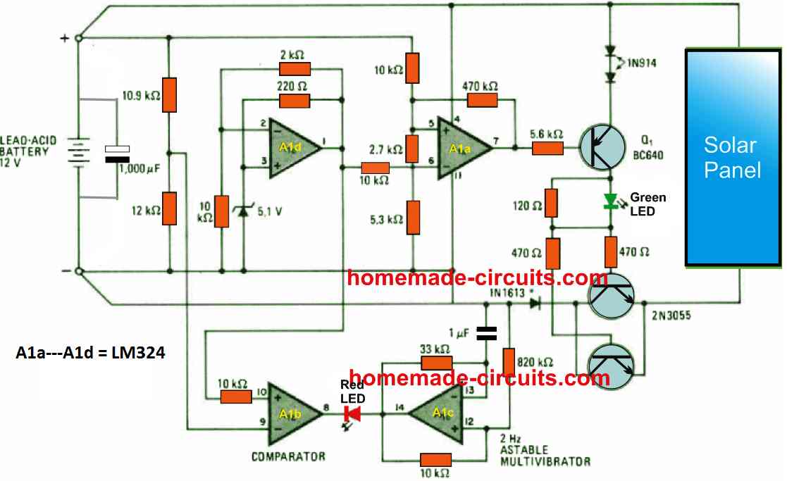
Transistors Q1, Q2, and Q3 turn on when the battery voltage falls below 13.5 volts, which is typically the open-circuit voltage of a 12 V battery. At that point, the solar panels get the required charging current.

The battery is charging as shown by the green LED that is on. Op amp A1a turns off transistors Q1–Q3 as the battery terminal voltage approaches the solar panel's open-circuit potential.

This state of affairs remains locked until the battery voltage falls below 13.2 V, at which point the battery charging procedure is once more initiated.

When there is no solar panel present and the battery voltage continues to drop from 13.2 V to about 11.4 V, which indicates that the battery is completely depleted, the output of A1b flips to 0 V, which causes the associated red LED to flash at a rate set by the astable multivibrator A1c.

flashing in this case at a rate of two hertz. To maintain the switching thresholds at the 11.4 V and 13.2 V levels, Op amp A1d provides a reference of 6 V.

The LM324 regulator circuit under consideration is engineered to handle currents as high as 3 amps.

In order to ensure that all of these transistors can sustain saturation during the charging sessions, it might be necessary to increase the base currents of Q2 and Q3 in order to work with more considerable currents.

You'll also like:

  • 1.  How to Make a Solar Fence Charger Circuit
  • 2.  How to Make a Home Solar Electricity Set up Circuit for an Off-the-grid Living
  • 3.  Make this Solar Charger Circuit with Auto Cut-Off Using Only Transistors
  • 4.  Simple Solar Plant Watering Alarm Circuit
  • 5.  How to Build a Self Optimizing Solar PWM Charger Circuit with Buck Converter
  • 6.  Best Low Drop Solar Charger Circuits Explained

About Admin

Hey friends, Thanks a bunch for stopping by this site! I am an engineer with a Bachelor of Engineering in Electronics and Telecommunication. One of my passions is gathering information from all sorts of electronics books and tutorials. I then take that information and compile it into a language that is super easy to understand. My goal is to make those complex electronics circuit concepts and technical terms much more accessible for all the new and budding electronics engineers out there. I can also design customized circuit diagrams as required by the users.
If you have any questions related to this field, please do not hesitate to drop a comment! I am always here and ready to help you out with any queries you might have. I cannot wait to hear from you!

Reader Interactions

Leave a Reply Cancel reply

Your email address will not be published. Required fields are marked *

Primary Sidebar

Categories

  • 3 Phase (4)
  • 8051 Microcontroller (1)
  • Arduino (11)
  • Audio and Amplifier (102)
  • Automation (8)
  • Battery Chargers (64)
  • Bicycle Projects (4)
  • Car and Motorcycle Projects (39)
  • Datasheets (10)
  • DIY Projects (5)
  • Electrical (15)
  • Free Energy (6)
  • Games Projects (2)
  • High Voltage (14)
  • Hobby Projects (30)
  • Household Circuits (2)
  • IC 555 Circuits (5)
  • Ignition Circuits (2)
  • Indicators (50)
  • Infrared (6)
  • Inverter Circuits (29)
  • Lights and Lamps (97)
  • Medical (8)
  • Meter and Tester Circuits (38)
  • Motor Driver (17)
  • New Circuits (56)
  • Oscillators (30)
  • Pets and Pests (5)
  • Power supply (80)
  • Protection Circuits (25)
  • PWM (9)
  • Remote Control (20)
  • Security and Alarm Circuit (48)
  • Sensors and Detectors (66)
  • Signal Processor (23)
  • Solar Controller Circuits (62)
  • SSR (3)
  • Temperature Controller (20)
  • Timer (25)
  • Transformerless (7)
  • Transmitters (12)
  • Tutorials (45)
  • UPS (2)
  • Voltage Regulators (57)
  • Water Sensor and Controller (29)
  • Home
  • Privacy Policy
  • Contact
  • Disclaimer
  • Copyright

© 2025 · Making Easy Circuits