• Skip to main content
  • Skip to primary sidebar

Making Easy Circuits

Learn and build electronic circuits

You are here: Home / Sensors and Detectors / Sound Operated Switch Circuit

Sound Operated Switch Circuit

Last Updated on November 17, 2024 by Admin 3 Comments

Sound triggered switches are employed in several applications, a few common illustrations being voice controlled tape recorders, baby alarms, burglar alarm systems, and VOX (voice managed switching) techniques of radio transmitting/receiving installations.

The straightforward sound operated switch circuit demonstrated here will probably work at a distance of up to around 2 or 3 metres from a voice of average volume (slightly-less in case the xtal microphone insert is substituted with a medium or high impedance powerful sort).

fig1 35

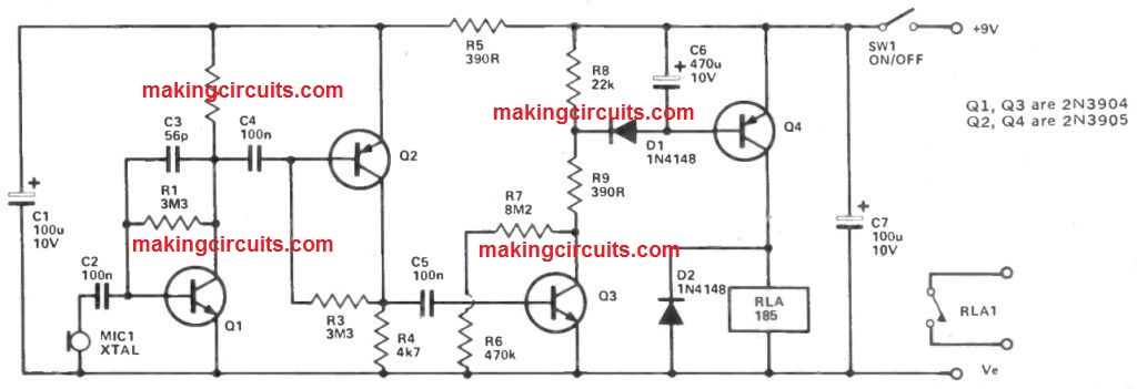
Signals generated by the microphone are amplified by a high gain amplifier which employs two stages of common emitter amplification. These two stages depend on Q1 and Q2 and work with a simple capacitively combined set up.

Both transistors are controlled at low collector currents so as to provide a low noise level and quiescent current usage. C3 rolls off the high frequency response of the circuit and assists great firmness.

The output from Q2 is connected to a third common emitter stage through C5. This third stage is dependent on Q3, and is biased by R6 and R7 to a point where Q3 is practically cut off.

There is hence hardly any voltage produced around load resistor R8, and the input voltage fed to Q4 through D1 is inadequate to switch on this device and trigger the relay which often forms its collector load.

Nevertheless, when sounds are obtained through the microphone, a sturdy signal is acquired at Q3's base, leading to it to perform intensely on positive going input half cycles.

This constitutes a series of powerful negative pulses across C4, charging up this component to a sufficient level to turn on Q4 and the relay.

A set of relay contacts are applied to regulate the supply to the slave devices. C4 charges through the pretty low impedance of Q3 and R9, supplying the circuit pretty quick attack time. C4's release path is with the fairly high impedance of Q4's base emitter junction providing an decay time of a second or two.

Hence the sound operated switch circuit reacts swiftly each time a signal is at first obtained, however the relay will not cut out during the brief pauses that take place while in regular speech.

The consumption of circuit's quiescent current is just around 250 uA, however this increases to around 35mA once the relay is triggered.

You'll also like:

  • 1.  People and Object Counter Circuit
  • 2.  How to Make a Differential Temperature Detector/Controller Circuit
  • 3.  Metal Detector Circuit using a Single IC
  • 4.  Under Soil Gold Detector Circuit
  • 5.  Static Electricity Detector Meter Circuit
  • 6.  How to Measure Thunderstorm Distance using an Electronic Circuit

About Admin

Hey friends, Thanks a bunch for stopping by this site! I am an engineer with a Bachelor of Engineering in Electronics and Telecommunication. One of my passions is gathering information from all sorts of electronics books and tutorials. I then take that information and compile it into a language that is super easy to understand. My goal is to make those complex electronics circuit concepts and technical terms much more accessible for all the new and budding electronics engineers out there. I can also design customized circuit diagrams as required by the users.
If you have any questions related to this field, please do not hesitate to drop a comment! I am always here and ready to help you out with any queries you might have. I cannot wait to hear from you!

Reader Interactions

Comments

  1. Martin says

    May 28, 2021 at 8:06 pm

    Thank you. I appreciate it.

    Reply
  2. Martin Weisenbacher says

    May 20, 2021 at 1:22 am

    What is the value for the missing “R2”? I see a symbol for a resistor, but there is no value depicted.

    Reply
    • admin says

      May 28, 2021 at 6:17 pm

      Yes it can be a 100k resistor….mistakenly the value is not printed

      Reply

Leave a Reply Cancel reply

Your email address will not be published. Required fields are marked *

Primary Sidebar

Categories

  • 3 Phase (4)
  • 8051 Microcontroller (1)
  • Arduino (11)
  • Audio and Amplifier (102)
  • Automation (8)
  • Battery Chargers (64)
  • Bicycle Projects (4)
  • Car and Motorcycle Projects (39)
  • Datasheets (10)
  • DIY Projects (5)
  • Electrical (15)
  • Free Energy (6)
  • Games Projects (2)
  • High Voltage (14)
  • Hobby Projects (30)
  • Household Circuits (2)
  • IC 555 Circuits (5)
  • Ignition Circuits (2)
  • Indicators (50)
  • Infrared (6)
  • Inverter Circuits (29)
  • Lights and Lamps (97)
  • Medical (8)
  • Meter and Tester Circuits (38)
  • Motor Driver (17)
  • New Circuits (56)
  • Oscillators (30)
  • Pets and Pests (5)
  • Power supply (80)
  • Protection Circuits (25)
  • PWM (9)
  • Remote Control (20)
  • Security and Alarm Circuit (48)
  • Sensors and Detectors (66)
  • Signal Processor (23)
  • Solar Controller Circuits (62)
  • SSR (3)
  • Temperature Controller (20)
  • Timer (25)
  • Transformerless (7)
  • Transmitters (12)
  • Tutorials (45)
  • UPS (2)
  • Voltage Regulators (57)
  • Water Sensor and Controller (29)
  • Home
  • Privacy Policy
  • Contact
  • Disclaimer
  • Copyright

© 2025 · Making Easy Circuits