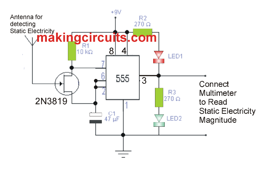
Through this particular little electronic circuit we are able to achieve an effective research laboratory instrument. The circuit indicates using the flashing of the LEDs when there's an electrostatic fields available. The frequency with which the LEDs flash shows proportionally the magnitude of existing static field.
The circuit operates using a FET transistor, as a result of its high impedance varies its actions together with the small current of electrons delivered by the antenna with which static electricity is captured. As soon as the FET varies its electrical resistance in accordance with the input current via the gate, the integrated circuit 555 accordingly varies the switching frequency of the LEDs. Be aware that the integrated circuit is set up using a fundamental oscillator, in which the frequency relies on the values of the capacitor C1 and the resistor R1 between pins 6 and 7, between which the FET transistor has been mounted.
Furthermore, the circuit possesses a couple of output terminals that offer a variable frequency signal whose average magnitude is proportional to the level of static electricity existing across these terminals. A multimeter could be attached for the measurement and quantitative evaluation of the detected static electricity.
Isn’t it appropriate to maintain a high input impedance of 2N3819?
This impedance can be drastically reduced by traces of flux and other contaminants, especially at higher air humidity.
The impedance of this transistor is higher than 10¹² ohm.
You are correct! Thanks for your valuable feedback…
I build it on a PCB this time, but still, it does not work as intended. This proves to me that loose connections are not the problem, if there where any in case of the breadboard. Also the parts are soldered as close as possible and the lead lenghts are as short as possible. I think the schematic needs little adjustments. Have you actually build it yourself or just designed it? I would like to know your experience with the circuit so we can improve it even further.
I dd not check it practically, but the circuit looks good to me and should work. You can try removing the red LED and check again. You can can also try putting a 0.1uF capacitor across the gate and source of the FET
So the leds light up simultaneously with a frequnecy of 4Hz. If I put a 0.1uF cap beetween the gate and the source as you suggested, the frequency goes down to about 2Hz.
I haven’t tryed removing the red LED as I need them both for the measurement of the charge, be it positive or negative, don’t I? Anyway I searched the internet for another schematic some time ago and I found one that is identical to the one you posted here, but the description of how it works is somewhat backwards to what you say. I tryed serching again for it, but I can’t seem to find it anymore. Anyway I will try simpler schematics and go from there.
OK no problem, thanks for updating the info.
Hi there , I have build the circuit, but instead of the 2N3819 transistor I have used the IRF9620 because that is what I had around. Unfortunately when I power it up, the two leds light up togheter, without even bringing anything close to the antenna. When I bring a charge close to the antenna, nothing happens, the leds stay lit as before.
What can I do to make it work?
IRF9620 will not work, you must use an N-channel FET as mentioned in the diagram or you can try an equivalent such as BS170
Hello again,
I tryed it with 2N3819, but still, it doesn’t work. The 2 leds keep lighting up about 2 sec each, alternatively. I checked the connections, they are good. What could be wrong?
how did you build it? Did you build it on breadboard? breadboard is not recommended….build it by soldering the parts on a strip board.
Also try without an antenna.
Yes, I build it on a breadboard. I also tryed without the antenna and still, I have the same results. I will try designing a pcb and also ordering one, fix the components on it and I will come back with results.
OK, please try it by soldering the parts as close as possible and by keeping the lead length as short as possible.