• Skip to main content
  • Skip to primary sidebar

Making Easy Circuits

Learn and build electronic circuits

You are here: Home / Remote Control / Switch ON/OFF any Appliance Remotely using Mains Wiring

Switch ON/OFF any Appliance Remotely using Mains Wiring

Last Updated on November 2, 2020 by Admin Leave a Comment

Using the explained transmitter and receiver circuits, you can quickly exploit the existing mains home AC wiring to send signals across different rooms, for remotely switching ON/OFF any desired appliance such as lights, fans ACs, heaters, between rooms of your house.

This home power line remote controller circuit combines the transmitter and receiver protocols based on your home’s mains power network for remote control of the single-phase household appliances.

Transmitter Circuit

In the first figure below, a transmitter is represented. This device overlaps a 36 kHz signal on the 50 Hz AC voltage of your home when switch S1 is actuated.

Then, IC1 is supplied the voltage from the mains through rectifier circuits that comprise D1, D2, Zener diodes D3 and D4, and a filtering capacitor C4. We recommend to set up the circuit with +20V supply concerning the mains network-neutral (0V) line.

The opamp generates the 36 kHz signal and it is channeled to the mains using a coupling capacitor, C3. A bleeder resistor, R3, is used to discharge C1 and C2 when you uncouple the circuit from the AC voltage.

Receiver Circuit

In the next receiver circuit diagram below, it is supplied with a cost-effective doorbell transformer but any other power supply that can give out 6 to 8 V AC at around 0.3 A works just fine.

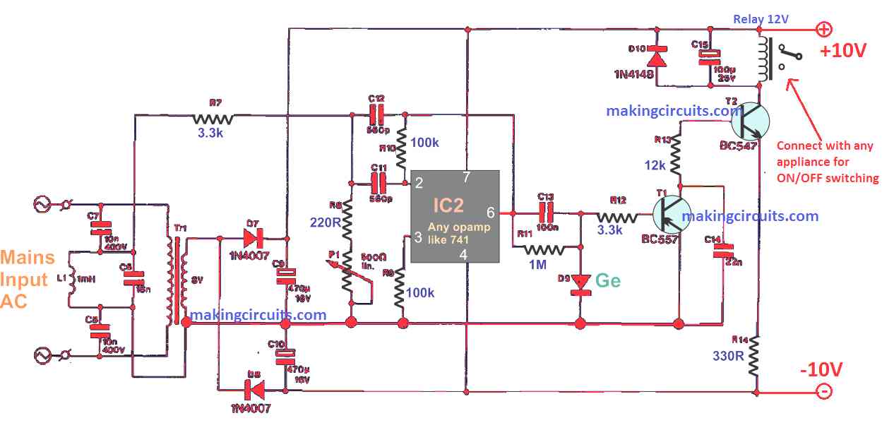
Besides driving Tr1, the AC voltage with the 36 kHz carrier is filtered by a circuit of L1-C6 which is connected in parallel.

This small section of the entire network functions to sense the existence of the overlapped 36 kHz carrier which is directed to amplifier IC1 through resistor R7.

After effective rectification by D9, the relay driver circuit which consists of T1 and T2 becomes enabled to energize Re1.

D9 should be preferably a germanium diode such a OA79 or similar. If you don't get this, a simple 1N4148 might do the job as well.

Afterwards, preset P1 is regulated to determine the correct cooperation between the sensitivity of the receiver and the noise resistance. When choosing the value for R14, make sure to consider first the relay coil current.

How to Install

Fundamentally, the implementation of this Power line AC remote controller circuits an entirely secure con-ABS case is utilized to avoid accidental contact with the AC voltage wires.

This step is always obligatory when working with any mains voltage circuits.

After this is verified, the transmitter can be mounted on a spare adaptor case with a small opening for attaching switch S1.

The ABS case of the receiver is expected to bigger if the mains socket is included for simpler connectivity with the household appliance to be controlled.

Be mindful of the rating of relay Re1 if you plan to switch heavy loads, like the coffee machine which houses a current of 4A.

You'll also like:

  • 1.  IR Remote Controlled Door Lock Circuit
  • 2.  How to Make a Ultrasonic Remote Control Circuit
  • 3.  433 MHz Encoder and Decoder Pinouts Explained
  • 4.  How to Build a Remote Controlled Night Lamp Circuit with Timer
  • 5.  Remote Controlled Fan Dimmer Switch Circuit
  • 6.  GSM based Irrigation Circuit using Cellphone missed Calls and Arduino

About Admin

Hey friends, Thanks a bunch for stopping by this site! I am an engineer with a Bachelor of Engineering in Electronics and Telecommunication. One of my passions is gathering information from all sorts of electronics books and tutorials. I then take that information and compile it into a language that is super easy to understand. My goal is to make those complex electronics circuit concepts and technical terms much more accessible for all the new and budding electronics engineers out there. I can also design customized circuit diagrams as required by the users.
If you have any questions related to this field, please do not hesitate to drop a comment! I am always here and ready to help you out with any queries you might have. I cannot wait to hear from you!

Reader Interactions

Leave a Reply Cancel reply

Your email address will not be published. Required fields are marked *

Primary Sidebar

Categories

  • 3 Phase (4)
  • 8051 Microcontroller (1)
  • Arduino (11)
  • Audio and Amplifier (102)
  • Automation (8)
  • Battery Chargers (64)
  • Bicycle Projects (4)
  • Car and Motorcycle Projects (39)
  • Datasheets (10)
  • DIY Projects (5)
  • Electrical (15)
  • Free Energy (6)
  • Games Projects (2)
  • High Voltage (14)
  • Hobby Projects (30)
  • Household Circuits (2)
  • IC 555 Circuits (4)
  • Ignition Circuits (2)
  • Indicators (50)
  • Infrared (6)
  • Inverter Circuits (29)
  • Lights and Lamps (97)
  • Medical (8)
  • Meter and Tester Circuits (38)
  • Motor Driver (17)
  • New Circuits (56)
  • Oscillators (30)
  • Pets and Pests (5)
  • Power supply (81)
  • Protection Circuits (25)
  • PWM (8)
  • Remote Control (20)
  • Security and Alarm Circuit (48)
  • Sensors and Detectors (66)
  • Signal Processor (23)
  • Solar Controller Circuits (61)
  • SSR (3)
  • Temperature Controller (20)
  • Timer (25)
  • Transformerless (7)
  • Transmitters (12)
  • Tutorials (45)
  • UPS (2)
  • Voltage Regulators (57)
  • Water Sensor and Controller (29)
  • Home
  • Privacy Policy
  • Contact
  • Disclaimer
  • Copyright

© 2025 · Making Easy Circuits