Zero-voltage switching (ZVS) for triacs is implemented by providing a controlled power to the load, through an ON/OFF switching of the line voltage, which is specifically at the zero crossing thresholds of the sine wave. The frequency of the switching determines the control power to the load.
This method alleviates the constraints of Radio Frequency Interference (RFI) that is related to the phase regulation of great resistive loads.
Difference between Triac Zero-Voltage Switching and Phase Control
Figure below describes the difference between phase control and zero-voltage switching in which the higher waveform depicts phase control while the lower waveform displays zero-voltage switching.
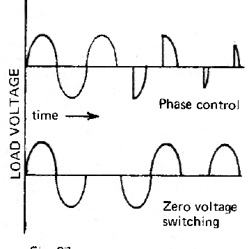
Only distinct applications that allow the controlled load to average bursts of whole half-cycles are utilized for zero-voltage switching.
Therefore, the reaction time of the load must be longer than the interval of the switching cycle.
This is because, at low-power configurations, short bursts between 20 to 30 half-cycles can be practical at 10 seconds pauses.
Hence, the approach is suitable for the regulation of loads like heating elements but not for dimming of the light.
Half-wave Phase Control
The next figure below shows an efficient but easy zero-voltage switching example. This circuit delivers only half-wave control, yet it is extremely apt for commercial usages in which the design of heating elements is flexible.
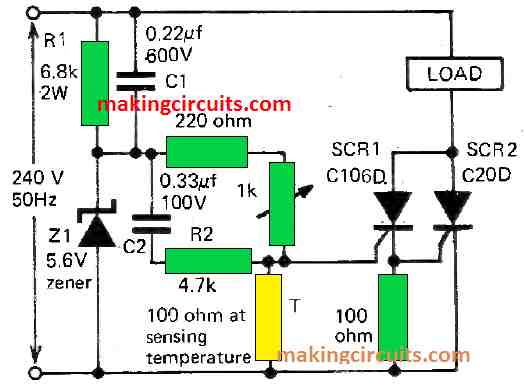
Even though there is a huge deviation in line voltage and ambient temperature, the integrity of the circuit is held steady and robust. The reaction time rests on the properties of the thermistor which is compounded normally by 1 or 2 seconds.
The sensing discrepancy is about 0.25°F at typical surrounding temperature.
Zener diode Z1 develops a nominal base voltage value of 5.6 V by slashing the incoming positive half-cycle of the mains voltage.
This base or pedestal is separated by R2, C2 and associated resistors to create a pedestal of shortened amplitude with an overlaid pulse on top of the base.

The waveform is enforced to the gate of SCR1. A forward phase alteration to the base is supplied by capacitor C1, which is also parallelly linked to R1.
This allows conduction of SCR1 by the summit of the positive decaying pulse that is overlapped on the pedestal. The whole process is carried out at the start of the forward travelling half-cycle of line voltage that forms at the anodes of the pair of SCRs.
The thermistor governs the amplitude of the base and delivers a half-proportional control with minimum temperature deviation.
The containing setup of the SCR1 and SCR2 lessens the implications of the surrounding temperature uncertainties. In terms of cost, this circuit is relatively cheaper compared to a phase-control circuit of a similar power handling capability because no RFI parts are needed.
Full-wave Phase Control
Figure below describes a circuit that will deliver a full-wave control of heating loads of various dimensions.
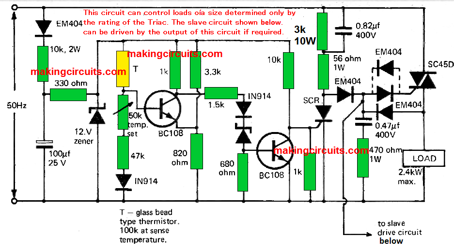
The activating circuit will power Triacs of different size from 1A to 125A. Furthermore, you can connect any number of Triacs as slaves to the principal activating circuit. The following depicts the activating circuit below.
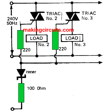
The temperature variation of this circuit design is almost ± 0.167°C. Additionally, a semi-proportional function is found in this circuit and it is suitable for conditions where relatively large volumes of power must be regulated and at a low cost.
Zero Crossing Control
Several organisations have manufactured integrated circuits, especially for triac zero-voltage switching procedures.
These ICs allow a more effective way of managing the operational procedures without incorporating a large number of electronic parts.
An example of a standard zero-voltage switching integrated circuit is the µ742 fabricated by Fairchild Semiconductor.
When utilized with the several other components and a thermistor, this IC recognizes sensor imbalance, senses the zero-voltage passing line and generates the essential Triac-activating pulse.
This sort of zero-voltage switching integrated circuits can be introduced to incredibly complex triac based applications like the “fail-safe” regulation of heating and refrigerating loads.
The breakdown of a thermistor or a resistance thermometer can result in a disaster for numerous control systems.
For example, a heating regulator with negative temperature coefficient would construe shorted thermistor leads as excessive temperature and as a result, it would kill the supplied power.
In an unfortunate event, if the thermistor had an open circuit due to unclear reasons, the control system would recognize a low-temperature and allow complete power to the load.
To safeguard the system from catastrophes like this, an “open circuit” sensor is extremely crucial.
Such a protection circuit is displayed in the figure below. With minimal adjustments, the same circuit can be utilized to safeguard the risks against “short circuit” conditions caused by the breakdown of positive temperature coefficient thermistors.
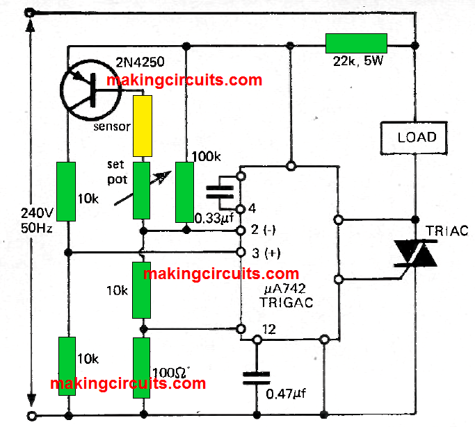
For single and 3-phase loads, zero-voltage switching can be applied safely in line with relative control circuitry, although these systems are quite sophisticated in nature and fall under a new topic of discussion.
More information of circuits of this type can be retrieved from the makers of zero-voltage switching ICs.
Triacs – Fault finding
From an electrician’s perspective, Triacs are straightforward electronic components. Their condition is always binary – functional or dysfunctional.
The biggest reason why a Triac fails is because of an overload. Like most semiconductors, it is vital to know that a short-circuit across its output almost instantly kills the device.
One of the convincing ways to detect an overloaded Triac is a lost gate control which puts the component at an “always-on” condition.
This condition can be easily inspected by unsoldering any leads that are attached to the Triac’s gate, and if the unit is still powered up, that means gate control is lost.
Just ensure that the load has no short circuit by verifying it using an ohmmeter and only after that attempt to replace the Triac.
When the operation is resumed, observe the line current of the circuit to make sure it stays in the Triac’s rating from the datasheet.
Be vigilant that the giant radiant globes have an incredibly high inrush current that may surpass the temporary overload limit of Triac, which is generally 5-10 times the full-rated load for a half-cycle input waveform.
Another significant breakdown is when the Triac circuit does not get activated completely. Usually, this is caused by a problem during activation and not the Triac itself.
The first apparent step is to inspect if there is mains voltage present across the Triac.
Let’s say there is voltage, a swift way to examine it is by placing a 150- or 1kΩ resistor between the gate and the case. This ought to activate the Triac into conduction mode.
When the Triac is activated and conducts, it means the problem is with the activating circuits. If Triac is not activated, that implies the component is defective.
Most importantly, do not examine a Triac with a Megger.
Sunil says
I am looking for triac to be use for switching only positive half cycle and negative half cycle when triggered through microcontroller can some one help with schematic