With this logic probe circuit the user will be able to verify the various logic levels in a given digital circuit, and help him to diagnose a given fault in the circuit.
What is a Logic Level
In digital circuits, a logic level refers to voltage levels which may be either "high logic" or a "low logic", intermediate or undefinde level between these thresholds are ignored or considered and invalid.
A high logic refers to a voltage level that may be equal to the available supply voltage level, generally applied to the Vcc of the specific ICs,whereas a logic low is referred to a zero voltage level corresponding to the ground line or the negative supply from the power supply, generally connected with the Vss of the concerned IC in the circuit.
Technically any voltage that may be above 2V or between 2V and the supply voltage is considered as a high logic, and anything below 1V is considered as a logic logic, whereas the in between levels are considered invalid, which may lead to abnormal results from a digital circuit.
How the Logic Tester Works
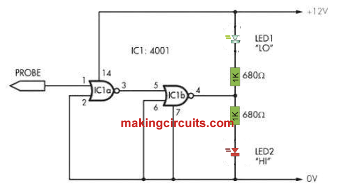
Referring to the shown figure, the design utilizes a digital IC for the implementation. Being a digital IC itself it is able to recognize and presnt the results in a better way. Second good thing is that, since the probe is connected with the input of the digital gate, it presents a high impedance and prevents any form of loading on the circuit which is being tested. This ensures better outcome and a safe logic level testing approach.
Only a couple of agtes from the IC 4001 is used for the implementation, however you can use any similar digital CMOS IC gates for making a logic probe tester circuit.
Since one of the inputs of the first gate is used as the probe and while it is unconnected the gate become highly unstable, and as a result it creates a random logic level for the other gate input, which in turn outputs a erratic signal to the LEDs.
Both the LEDs consequently remain lit showing no defined logic level at the probe end.
However when the logic probe is touched with a logic supply, depending upon the logic level either of the LEDs become solid and illuminated and the other LED is shut off, indicating the corresponding logic at the point where the probe is introduced.
When a high logic is detected at the probe end, the green green LED is illuminated while the red is shut off, and conversely when a low logic is sensed by the probe, the green LED is shut off and the red LED is quickly illuminated.
In this way the user or the technician is able to distinguish between 3 levels, ie an open or undefined logic level with both the LEDs ON, a low logic when the red LED is ON and green is OFF, and a high logic when the green LED is ON and the red LED is OFF.
Leave a Reply