This easy circuit will allow you to imagine distant thunder lightning by means of a in the same way choreographed LED is shown, precisely in keeping with the lightning which may be happening anywhere in the distant sky, the reply is going to be simultaneous therefore a lot prior to the sound that could achieve your ears after a few seconds.
Thunder lightnings are essentially such as huge electric arcs, thereby produce a proportionate amounts of large RF signals in the ether each time these flash in the sky.
The tiny RF detector circuit which has been in the beginning created for capturing cell phone RF waves, could possibly be as efficiently useful for the offered lightning detector design furthermore.
Parts List
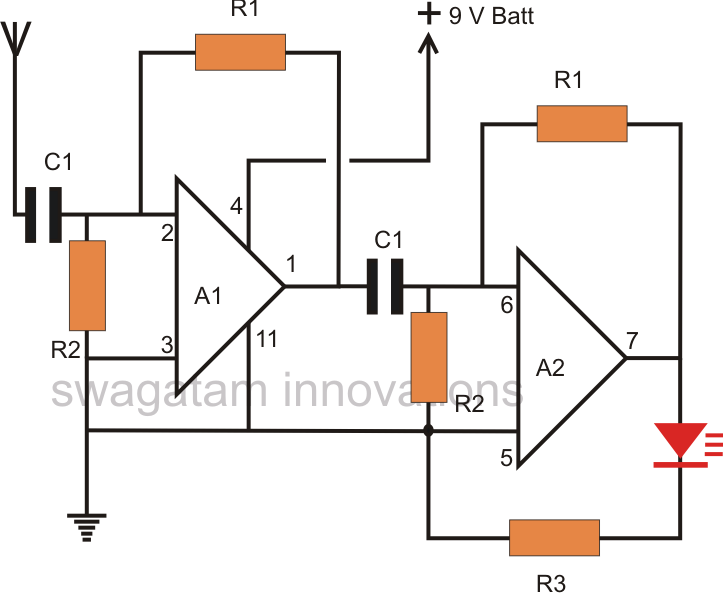
R1 = 2M2,
R2 = 100K,
R3 = 1K,
C1 = 0.01uF
A1, A2 = IC 324
Talking about the above effortless thunder lightning detector circuit, the design is essentially a couple of opamps from the IC LM324 wired up as a high gain amplifier circuit.
The antenna may very well be a meter long flexible wire utilized right here for obtaining the RF disruptions from the thunder lightning arcs.
Considering that the circuit is a high gain amplifier, it may well turn out to be very easily disappointed and provide incorrect outcomes if some things are not looked after.
All the interconnections ought to be as compact as possible, and the PCB ought to be carefully cleaned with thinner to be able to take away any kind of flux residue which may elsewhere produce malfunctioning of the circuit.
After creating the above design, at first you should not hook up any wire to the antenna terminals.
Make certain the LED continues close off after the circuit is operated, and utilize a 9V PP3 battery for operating the circuit, an AC/DC adapter is useless when you might find the LED constantly ON if a mains adapter is utilized.
Subsequent, take a gas lighter and click the device with its tip held near the antenna point of the circuit.
You ought to discover the LED lighting and flashing as a reaction to every clicking of the gas lighter.
This could establish a properly developed detector circuit.
Lastly, you may connect the 1 meter long antenna wire to the demonstrated position and wait for a potential thunder lightning hits in the vicinity.
You are going to be amazed to observe the LED dance and flash specifically in tandem with the lightning illumination sequences.
You can enhance the Led reply by adding an opto coupler and a corresponding high watt lamp with the circuit, such that the entire room gets dazzled each and every time the lightning is displayed in the sky..
We need help for made it so what to do
The value of R1 should be how much R1= 2M2 means??
2.2 meg ohm