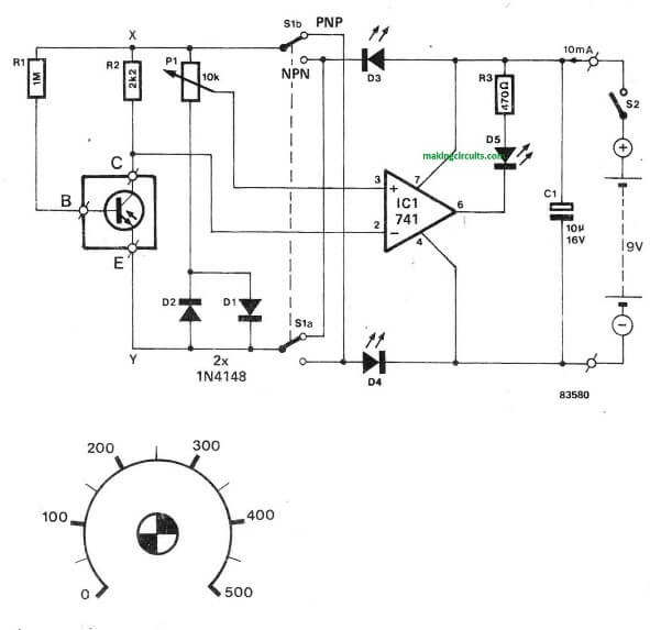
This hFE or transistor forward gain tester is intriguing due to its ease-of-use and because it allows the use of both PNP and NPN transistors to be assessed.
Additionally more the measuring becomes self-governing of the supply voltage of the tester. As the picture displays, the base current of the transistor under check moves through R1. lts base current Ig is therefore add up to the voltage drop along the collector resistor is hpg x lg x R2. P1 can be used to establish a reference voltage produced from voltage UXY — UD1 (or D2 for a PNP transistor).
Because of this the setting up of the potentiometer will be specifically relative to the hFE or the current gain of the transistor being tested and is also independent of source voltage.
The voltage throughout R2 and also the voltage fixed with P1 are investigated by IC1 that is attached as a comparator. Potentiometer P1 is at this point arranged such that the LED at the output of the op-amp merely lights or is just dimmed.
During this setting the voltage over the potentiometer add up to the voltage around R2. Switch S1 is applied to switch from NPN to PNP (or vice versa) by simply reversing “the polarity of voltage UXY. LEDs D3 and D4 in the source lines guarantee how the input voltages to be assessed are inside the common mode range of the op-amp utilized.

Leave a Reply