• Skip to main content
  • Skip to primary sidebar

Making Easy Circuits

Learn and build electronic circuits

You are here: Home / Voltage Regulators / Two Transistor Voltage Doubler Circuit

Two Transistor Voltage Doubler Circuit

Last Updated on December 28, 2021 by Admin 4 Comments

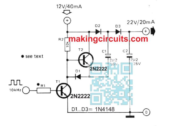
The following small circuit will create a DC output that may be nearly 2 times the supply voltage. A square wave input is necessary of adequate amount to switch T1 totally on / off.

As soon as T1 is switched ON, C1 is charged to slightly below the supply voltage.

As soon as T1 is cut off, T2 is switched ON and this boosts the voltage on the negative terminal of C1 to just below the positive supply level.

This suggests that the voltage on the positive end of C1 is elevated to virtually two times the supply voltage, in order that C2 will eventually charge to this degree.

The circuit is amazingly efficient: the current consumed through the main supply is barely higher than double the output current. In the illustration demonstrated here, the efficiency is around 90%.

The value for R1 is determined by the amplitude of the square wave input: T1 may call for a base current of 0.5 - 1 mA.

two transistor voltage doubler circuit

You'll also like:

  • 1.  Getting More Current from 78XX Voltage Regulators in Parallel
  • 2.  How to Build a 3 Phase VFD Circuit
  • 3.  Customizable Fixed Voltage Regulator Circuit using Opamp
  • 4.  Voltage Doubler Circuit Using IC 4049 NOT gates
  • 5.  2 in 1 Light Dimmer Circuit with Touch Pad Operation
  • 6.  Designing a IC 723 Power Supply with Variable Voltage and Current

About Admin

Hey friends, Thanks a bunch for stopping by this site! I am an engineer with a Bachelor of Engineering in Electronics and Telecommunication. One of my passions is gathering information from all sorts of electronics books and tutorials. I then take that information and compile it into a language that is super easy to understand. My goal is to make those complex electronics circuit concepts and technical terms much more accessible for all the new and budding electronics engineers out there. I can also design customized circuit diagrams as required by the users.
If you have any questions related to this field, please do not hesitate to drop a comment! I am always here and ready to help you out with any queries you might have. I cannot wait to hear from you!

Reader Interactions

Comments

  1. Dui says

    December 23, 2021 at 1:12 pm

    Hello, i want to ask which one is C3? is it typo? thanks

    Reply
    • admin says

      December 28, 2021 at 10:16 am

      Hello, yes there is a mistake. Actually C1 is wrongly mentioned as C2, and C2 is wrongly mentioned as C3…there’s no C3.

      I will correct it soon.

      Reply
  2. Ben says

    February 20, 2021 at 5:45 pm

    Hi, mine is a question. Can i use a larger transistor so as to get higher output current from the circuit

    Reply
    • admin says

      February 20, 2021 at 9:13 pm

      Hi, changing only transistors will not help, you will have to increase the capacitor value also, because it is the capacitor uF that decides the output current

      Reply

Leave a Reply Cancel reply

Your email address will not be published. Required fields are marked *

Primary Sidebar

Categories

  • 3 Phase (4)
  • 8051 Microcontroller (1)
  • Arduino (11)
  • Audio and Amplifier (102)
  • Automation (8)
  • Battery Chargers (64)
  • Bicycle Projects (4)
  • Car and Motorcycle Projects (39)
  • Datasheets (10)
  • DIY Projects (5)
  • Electrical (15)
  • Free Energy (6)
  • Games Projects (2)
  • High Voltage (14)
  • Hobby Projects (30)
  • Household Circuits (2)
  • IC 555 Circuits (4)
  • Ignition Circuits (2)
  • Indicators (50)
  • Infrared (6)
  • Inverter Circuits (29)
  • Lights and Lamps (97)
  • Medical (8)
  • Meter and Tester Circuits (38)
  • Motor Driver (17)
  • New Circuits (56)
  • Oscillators (30)
  • Pets and Pests (5)
  • Power supply (81)
  • Protection Circuits (25)
  • PWM (8)
  • Remote Control (20)
  • Security and Alarm Circuit (48)
  • Sensors and Detectors (66)
  • Signal Processor (23)
  • Solar Controller Circuits (61)
  • SSR (3)
  • Temperature Controller (20)
  • Timer (25)
  • Transformerless (7)
  • Transmitters (12)
  • Tutorials (45)
  • UPS (2)
  • Voltage Regulators (57)
  • Water Sensor and Controller (29)
  • Home
  • Privacy Policy
  • Contact
  • Disclaimer
  • Copyright

© 2025 · Making Easy Circuits