• Skip to main content
  • Skip to primary sidebar

Making Easy Circuits

Learn and build electronic circuits

You are here: Home / Indicators / Universal LED Bar Graph Indicator Circuit

Universal LED Bar Graph Indicator Circuit

Last Updated on April 8, 2020 by Admin Leave a Comment

This universal pointer or LED bar graph indicator circuit can be used with any kind of input sensor that delivers a exponentially varying voltage. This can be for example from a temperature sensor, hygrometer and a battery that needs to be monitored whose output could be translated into an LED based bar graph indication for quick reading..

How the Circuit Works

The contents of the circuit are are an amplifier circuit IC1 and a display stage IC2.
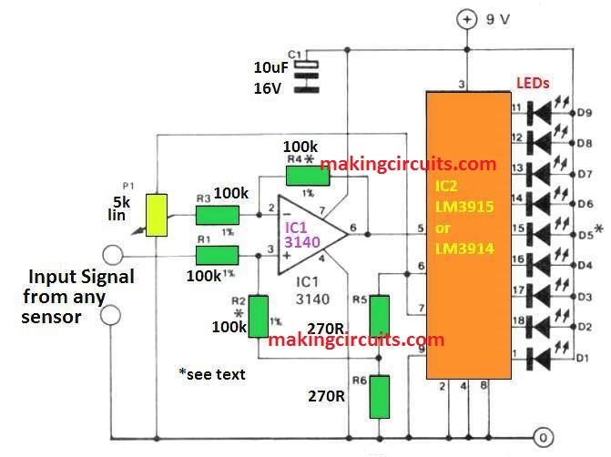
universal bar graph

There are about 3 to 9 LEDs in the display with Ds in the centre representing point of origin in yellow.

The LED is lit by adjusting the potentiometer P1. With the change in input voltages, different LEDs are lightened.

For example, when the voltage rises slightly, D6 illuminates and again when the voltage falls, D4 gets illuminated. The LEDs D7 D9 or D3 D0 may hardly be lit according to the variations in the input signals.

The color of the LEDs depends on its application. The illumination of the middle LEDs in the bar graph is appropriately adjusted by adjusting P1.

How to Calibrate

In order to read the input voltage directly through the LED illumination, the potentiometer can be provided with a graduated scale. To calibrate the scale accurately, apply voltages in steps of 0.1V. Turn the P1 till center lights and draw a thin line at the perfect position of P1.

1V is necessary at pin 5 of IC2 to light up D1 and D9, thus making the sensitivity of the IC important. 1V is required at the input of the LEDs to operate as the amplification of IC1 is unity (R4/R3).

The potential at the junction of R5 and R6 are added to the result after the voltage at the wiper of P1 is deducted by the Opamp IC1.

The reference voltage (1.28V) can be compensated for as it is connected to P1. The P1 is connected in series to the positive supply line with a suitable resistor. If the supply line is well regulated, the display will be stable.

Sensitivity Adjust

The input sensitivity is inversely proportional to the values of R4 and R2, however these values should be kept the same.

The current consumption is about 10 times the value of current through R5 and R6 and can be primarily determined by the current through the LEDs.

This current is equal to the on-chip reference voltage of 1.28V divided by the total resistance of R5+R6.

The total current must not exceed 50mA. The maximum current through the LEDs is about 40mA with the current in pin 7 limited to 4mA

You'll also like:

  • 1.  Mains Wiring Phase, Neutral, Earthing Tester Circuit
  • 2.  Simple Digital Voltmeter Circuit
  • 3.  20 watt, 5 watt Fluorescent Lamp Inverter Circuit
  • 4.  3 in 1 Circuit Fault Tester Circuit
  • 5.  Automatic Light Circuit for Washroom  
  • 6.  555 Timer Ramp Generator

About Admin

Hey friends, Thanks a bunch for stopping by this site! I am an engineer with a Bachelor of Engineering in Electronics and Telecommunication. One of my passions is gathering information from all sorts of electronics books and tutorials. I then take that information and compile it into a language that is super easy to understand. My goal is to make those complex electronics circuit concepts and technical terms much more accessible for all the new and budding electronics engineers out there. I can also design customized circuit diagrams as required by the users.
If you have any questions related to this field, please do not hesitate to drop a comment! I am always here and ready to help you out with any queries you might have. I cannot wait to hear from you!

Reader Interactions

Leave a Reply Cancel reply

Your email address will not be published. Required fields are marked *

Primary Sidebar

Categories

  • 3 Phase (4)
  • 8051 Microcontroller (1)
  • Arduino (11)
  • Audio and Amplifier (102)
  • Automation (8)
  • Battery Chargers (64)
  • Bicycle Projects (4)
  • Car and Motorcycle Projects (39)
  • Datasheets (10)
  • DIY Projects (5)
  • Electrical (15)
  • Free Energy (6)
  • Games Projects (2)
  • High Voltage (14)
  • Hobby Projects (30)
  • Household Circuits (2)
  • IC 555 Circuits (4)
  • Ignition Circuits (2)
  • Indicators (50)
  • Infrared (6)
  • Inverter Circuits (29)
  • Lights and Lamps (97)
  • Medical (8)
  • Meter and Tester Circuits (38)
  • Motor Driver (17)
  • New Circuits (56)
  • Oscillators (30)
  • Pets and Pests (5)
  • Power supply (81)
  • Protection Circuits (25)
  • PWM (8)
  • Remote Control (20)
  • Security and Alarm Circuit (48)
  • Sensors and Detectors (66)
  • Signal Processor (23)
  • Solar Controller Circuits (61)
  • SSR (3)
  • Temperature Controller (20)
  • Timer (25)
  • Transformerless (7)
  • Transmitters (12)
  • Tutorials (45)
  • UPS (2)
  • Voltage Regulators (57)
  • Water Sensor and Controller (29)
  • Home
  • Privacy Policy
  • Contact
  • Disclaimer
  • Copyright

© 2025 · Making Easy Circuits