• Skip to main content
  • Skip to primary sidebar

Making Easy Circuits

Learn and build electronic circuits

You are here: Home / Inverter Circuits / How to Upgrade a Low Power Inverter to a High Power Inverter using a Simple Circuit

How to Upgrade a Low Power Inverter to a High Power Inverter using a Simple Circuit

Last Updated on February 27, 2019 by Admin Leave a Comment

Here we find out about a number of easy circuit configurations which can change any specific low power inverter to an enormous high power inverter circuit.
You'll discover a lots of compact and medium sized inverters available in the market which range from 100 to 500 watts, the similar might be witnessed published within this blog. Improving such small or medium power inverters into substantial power in the order of kvas may appear quite a hard and complicated, but in fact it's not.
All inverter topologies fundamentally combine an oscillator frequency which can be then refined making use of power devices to high current levels before dumping into the step-up transformer for the final voltage raising techniques.
The existing amplifier stage which uses high current devices is actually where the upgrade ought to be completed in order to obtain any preferred power outputs from an inverter.
The most recent inveters heavily rely on mosfets for the aforementioned power modification stage, however BJTs may be as well useful for the similar very successfully, in reality much reliably than mosfets...
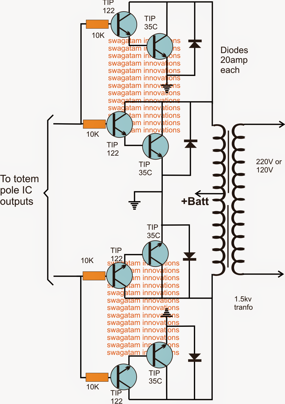
The following diagram indicates an easy and very efficient power output stage which is often built-in with any totem pole IC outputs for example IC 4047, IC TL494, IC SG3525, IC 4017 (clocked with IC555), for getting upto 1.5kva conversions.
The key devices in the circuit are the composition of the TIP122 and TIP35 which turn out to be a high gain, high current transistor pair, in a position to improving current to the rated massive levels immediately.
Each such device module is rated to generate a minimum of 30 x 24 = 720 watts, so by including more such components in parallel any specific preferred kva range could be estimated from the configuration

low2Bto2Bhigh2Bpower2Binverter2Bupgrade2Bcircuit
Making use of BJTs can be very dependable and less complicated but quiet large, if space is your trouble and require the upgrade from low to high power inverter in the nearly all compact manners, then mosfets turns into the widely used option and could be wired as demonstrated in the following diagram:


mosfettransistordrivercircuit
The input is produced again from any totem pole IC outputs, the mosfets might be rated according to the most wanted upgrade from lower to the highest magnitudes.
The diode integration indicates a basic PWM insertion which happens to be optional, but could be utilized if a altered sine wave output meant to be incorporated into the upgrade.

You'll also like:

  • 1.  How to Correctly Calculate Solar Panel, Inverter, Battery Charger
  • 2.  How to Build a 48V Inverter Circuit
  • 3.  How to Make a Optimizing Grid and Solar Electricity in Parallel with an Inverter
  • 4.  12V 200 watt Inverter Circuit
  • 5.  100 watt Inverter Circuit Using 2N3055 Transistors
  • 6.  Simple 100 watt to 500 watt Inverter Circuit

About Admin

Hey friends, Thanks a bunch for stopping by this site! I am an engineer with a Bachelor of Engineering in Electronics and Telecommunication. One of my passions is gathering information from all sorts of electronics books and tutorials. I then take that information and compile it into a language that is super easy to understand. My goal is to make those complex electronics circuit concepts and technical terms much more accessible for all the new and budding electronics engineers out there. I can also design customized circuit diagrams as required by the users.
If you have any questions related to this field, please do not hesitate to drop a comment! I am always here and ready to help you out with any queries you might have. I cannot wait to hear from you!

Reader Interactions

Leave a Reply Cancel reply

Your email address will not be published. Required fields are marked *

Primary Sidebar

Categories

  • 3 Phase (4)
  • 8051 Microcontroller (1)
  • Arduino (11)
  • Audio and Amplifier (102)
  • Automation (8)
  • Battery Chargers (64)
  • Bicycle Projects (4)
  • Car and Motorcycle Projects (39)
  • Datasheets (10)
  • DIY Projects (5)
  • Electrical (15)
  • Free Energy (6)
  • Games Projects (2)
  • High Voltage (14)
  • Hobby Projects (30)
  • Household Circuits (2)
  • IC 555 Circuits (5)
  • Ignition Circuits (2)
  • Indicators (50)
  • Infrared (6)
  • Inverter Circuits (29)
  • Lights and Lamps (97)
  • Medical (8)
  • Meter and Tester Circuits (38)
  • Motor Driver (17)
  • New Circuits (56)
  • Oscillators (30)
  • Pets and Pests (5)
  • Power supply (80)
  • Protection Circuits (25)
  • PWM (9)
  • Remote Control (20)
  • Security and Alarm Circuit (48)
  • Sensors and Detectors (66)
  • Signal Processor (23)
  • Solar Controller Circuits (62)
  • SSR (3)
  • Temperature Controller (20)
  • Timer (25)
  • Transformerless (7)
  • Transmitters (12)
  • Tutorials (45)
  • UPS (2)
  • Voltage Regulators (57)
  • Water Sensor and Controller (29)
  • Home
  • Privacy Policy
  • Contact
  • Disclaimer
  • Copyright

© 2025 · Making Easy Circuits