• Skip to main content
  • Skip to primary sidebar

Making Easy Circuits

Learn and build electronic circuits

You are here: Home / Security and Alarm Circuit / Vibration Activated Alarm Circuit

Vibration Activated Alarm Circuit

Last Updated on November 17, 2024 by Admin Leave a Comment

The noise or vibration activated alarm circuit displayed in this article makes use of its pre-installed loudspeaker like a microphone while it is within the sland- by-state.


How the Circuits Works

The moment it picks up a noise that surpasses an adjustable tolerance point. it gets activated. This little. smart circuil may be used as an security alarm generator which responds to disturbances.

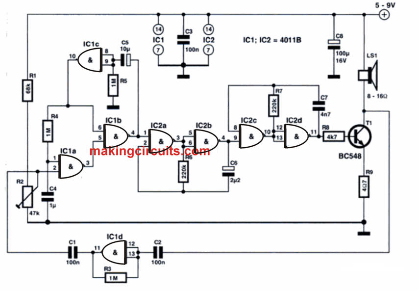
You may also put it to use to help you identify a physical object according to a noisy sound such as clapping both hands or whizzing noisally. The gate at the end of the schematic diagram works like a linear low-frequency amplifier because of the negative feedback resistor R3.

It obtains its input signal from loudspeaker LSI. that functions as a microphone whenever T1 is cut off. The amplified output signal through this gate goes by through Cl to a second IC 4011 gate which activates a monostable established by the a couple of gates positioned before & after CS and R5.

The DC threshold amount is put on pin 2 of IC1 via R2. This DC voltage is superimposed within the signal coming from Cl. Retriggering of the monostabie is averted by the collaboration of R4, C4 and thc first gate, additionally on which the sound generator IC1d stops the loudspeaker from behaving as a microphone as soon as it has been triggered.

A High output signal through pin 4 of the monostable makes it possible for a couple of astable multivibrators in IC2.

The first of these is a low-frequency generator which modulates the audio frequency tone generated by the second multivibrator. In this way a ‘siren' type of shrillsound that is heard from the loudspeaker. Ultimately Tl is powered via R8 to exert the loudspeaker pretty hard.

The loudspeaker current is restricted slightly little bit by R9. The length of the alarm signal depends upon the monostable time constant of R5 and C5. A Low logic on pin 4 of ICI obstructs the sound generator. Following the time delay established by R4 and C4 has ended. the loud-speaker yet again works like a microphone. The circuit could be driven with a 5 V to 9 V battery.


Circuit Diagram for the above Explained Vibration Activated Alarm Circuit


Circuit Diagram for the above Explained Vibration Activated Alarm Circuit

You'll also like:

  • 1.  Manufacturing Oxygen at Home – Circuit Diagram
  • 2.  Battery Low Voltage Alarm Circuit using NAND Gates
  • 3.  Basic Circuit for Making a Car Burglar Alarm
  • 4.  How to Make a Simple Motorcycle Security Alarm with Tilt Sensor
  • 5.  Fridge Alarm Circuit
  • 6.  Dog Barking Sound Simulator Circuit

Tagged With: Activated, Alarm, Vibration

About Admin

Hey friends, Thanks a bunch for stopping by this site! I am an engineer with a Bachelor of Engineering in Electronics and Telecommunication. One of my passions is gathering information from all sorts of electronics books and tutorials. I then take that information and compile it into a language that is super easy to understand. My goal is to make those complex electronics circuit concepts and technical terms much more accessible for all the new and budding electronics engineers out there. I can also design customized circuit diagrams as required by the users.
If you have any questions related to this field, please do not hesitate to drop a comment! I am always here and ready to help you out with any queries you might have. I cannot wait to hear from you!

Reader Interactions

Leave a Reply Cancel reply

Your email address will not be published. Required fields are marked *

Primary Sidebar

Categories

  • 3 Phase (4)
  • 8051 Microcontroller (1)
  • Arduino (11)
  • Audio and Amplifier (102)
  • Automation (8)
  • Battery Chargers (64)
  • Bicycle Projects (4)
  • Car and Motorcycle Projects (39)
  • Datasheets (10)
  • DIY Projects (5)
  • Electrical (15)
  • Free Energy (6)
  • Games Projects (2)
  • High Voltage (14)
  • Hobby Projects (30)
  • Household Circuits (2)
  • IC 555 Circuits (4)
  • Ignition Circuits (2)
  • Indicators (50)
  • Infrared (6)
  • Inverter Circuits (29)
  • Lights and Lamps (97)
  • Medical (8)
  • Meter and Tester Circuits (38)
  • Motor Driver (17)
  • New Circuits (56)
  • Oscillators (30)
  • Pets and Pests (5)
  • Power supply (81)
  • Protection Circuits (25)
  • PWM (8)
  • Remote Control (20)
  • Security and Alarm Circuit (48)
  • Sensors and Detectors (66)
  • Signal Processor (23)
  • Solar Controller Circuits (61)
  • SSR (3)
  • Temperature Controller (20)
  • Timer (25)
  • Transformerless (7)
  • Transmitters (12)
  • Tutorials (45)
  • UPS (2)
  • Voltage Regulators (57)
  • Water Sensor and Controller (29)
  • Home
  • Privacy Policy
  • Contact
  • Disclaimer
  • Copyright

© 2025 · Making Easy Circuits