• Skip to main content
  • Skip to primary sidebar

Making Easy Circuits

Learn and build electronic circuits

You are here: Home / Voltage Regulators / Voltage Doubler Circuit Using IC 4049 NOT gates

Voltage Doubler Circuit Using IC 4049 NOT gates

Last Updated on November 17, 2024 by Admin

Any DC source voltage (up to 15 V DC) may be doubled using the CMOS IC-based design below.

The proposed system can run applications at little above thirty mA of current and double any voltage between 4 and 15 V DC.

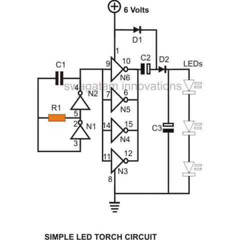
The schematic illustrates that this DC voltage doubler circuit utilizes a solitary IC 4049 to accomplish the intended outcome.
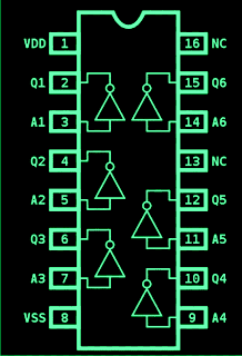
IC 4049 Pinouts

IC 4049 pinout diagram specifications

How the Circuit Works

All six of the IC 4049's gates work well together to provide the voltage doubling operations that are being explained. Six gates are included, two of which are set up as oscillators.

The oscillator part is located on the far left of the figure.

These two fundamental components—the 0.01 capacitor and the 100 K resistor—are what determine frequency.

When implementing voltage stepping-up operations, a frequency is essential, necessitating the use of an oscillator in this situation as well.

When a set of capacitors is initialized and discharged at the output, these oscillations become helpful. This is equivalent to increasing the voltage throughout the group of capacitors so that what emerges is two times the applied supply voltage.

But it is not ideal to apply the oscillator's voltage immediately to the capacitors; instead, it must pass via a set of parallel-arranged IC gates.

When these parallel gates are combined, they effectively buffer the frequency being utilized from the generator gates, making the subsequent frequency far more powerful in relation to current and able to withstand comparatively greater output load levels.

It is not possible to anticipate an output current managing capability more than 40 mA while adhering to the standards of a CMOS integrated circuit.

Higher loads beyond this can cause the voltage level to deteriorate in the direction of the supply voltage.

To achieve somewhat greater circuit efficiency ranges, the output capacitor numbers could be adjusted to 100uF.

This IC 4049 based voltage doubler circuit can produce an output of about 22 volts when supplied with a 12 volt supply input.

NOT gate voltage doubler circuit

Parts List

ReferenceValue
R168K
C1680pF
C2100uF/25V
C3100uF/25V
D11N4148
D21N4148
N1IC 4049
N2IC 4049
N3IC 4049
N4IC 4049
LEDs White3 nos.

You'll also like:

  • 1.  Zero Crossing 220V AC Light Dimmer Circuit using IC 555
  • 2.  5V 3 Amp Fixed Voltage Regulator Circuit using IC LM123 LM323
  • 3.  120V 220V Over Voltage and Under Voltage Cut OFF Circuit Explained
  • 4.  Incubator Heater Backup Circuit with Charger
  • 5.  12 V To 6 V Converter Circuit
  • 6.  Two Transistor Voltage Doubler Circuit

About Admin

Hey friends, Thanks a bunch for stopping by this site! I am an engineer with a Bachelor of Engineering in Electronics and Telecommunication. One of my passions is gathering information from all sorts of electronics books and tutorials. I then take that information and compile it into a language that is super easy to understand. My goal is to make those complex electronics circuit concepts and technical terms much more accessible for all the new and budding electronics engineers out there. I can also design customized circuit diagrams as required by the users.
If you have any questions related to this field, please do not hesitate to drop a comment! I am always here and ready to help you out with any queries you might have. I cannot wait to hear from you!

Primary Sidebar

Categories

  • 3 Phase (4)
  • 8051 Microcontroller (1)
  • Arduino (11)
  • Audio and Amplifier (102)
  • Automation (8)
  • Battery Chargers (64)
  • Bicycle Projects (4)
  • Car and Motorcycle Projects (39)
  • Datasheets (10)
  • DIY Projects (5)
  • Electrical (15)
  • Free Energy (6)
  • Games Projects (2)
  • High Voltage (14)
  • Hobby Projects (30)
  • Household Circuits (2)
  • IC 555 Circuits (4)
  • Ignition Circuits (2)
  • Indicators (50)
  • Infrared (6)
  • Inverter Circuits (29)
  • Lights and Lamps (97)
  • Medical (8)
  • Meter and Tester Circuits (38)
  • Motor Driver (17)
  • New Circuits (56)
  • Oscillators (30)
  • Pets and Pests (5)
  • Power supply (81)
  • Protection Circuits (25)
  • PWM (8)
  • Remote Control (20)
  • Security and Alarm Circuit (48)
  • Sensors and Detectors (66)
  • Signal Processor (23)
  • Solar Controller Circuits (61)
  • SSR (3)
  • Temperature Controller (20)
  • Timer (25)
  • Transformerless (7)
  • Transmitters (12)
  • Tutorials (45)
  • UPS (2)
  • Voltage Regulators (57)
  • Water Sensor and Controller (29)
  • Home
  • Privacy Policy
  • Contact
  • Disclaimer
  • Copyright

© 2025 · Making Easy Circuits