• Skip to main content
  • Skip to primary sidebar

Making Easy Circuits

Learn and build electronic circuits

You are here: Home / Water Sensor and Controller / Water Level Controller Using NAND Gates (IC 4093)

Water Level Controller Using NAND Gates (IC 4093)

Last Updated on November 17, 2024 by Admin Leave a Comment

In the discussed circuit, a logic IC 4093 is utilized. Commonly, the water we receive in our homes, which isnt pure, offers little resistance to electricity.

To put it plainly, water can conduct electricity, though the effect is very slight. Typically the resistance of household tap water falls between 100 K and 200 K ohms.

This level of resistance is sufficient for electronics and is harnessed in the project outlined in this article, specifically for a straightforward water level control circuit.

For the necessary detection, four NAND Gates are employed.

The entire process can be grasped through the following points:
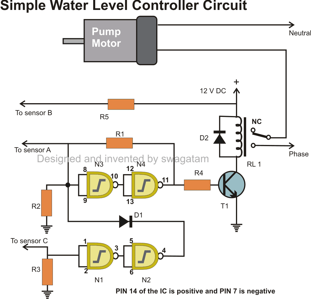
automatic water level controller circuit diagram using IC 4093 NAND gates
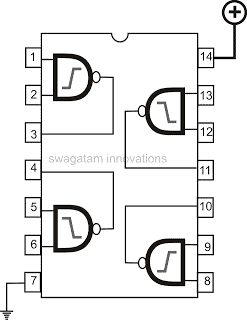
IC 4093 pinout details

How to Place the Sensors

Looking at the diagram, the point B is at a higher electrical level and is located towards the lower part of the tank.

Point C is right at the bottom and point A is attached to the very top.

If the water level stays below point B then both points A and C will have a neutral or zero electrical level.

This also keeps the inputs of certain NAND gates at a low electrical state due to the 2M2 resistors connected to them.
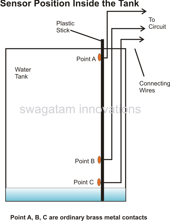
how to install water level sensor probes inside tank

How the Sensors Work

The NAND gate switches N2 and N4 are initially off so the relay and motor are off too.

Imagine the tank starts to fill up and when the water hits point B, it makes a connection with point C.

This turns on switch N1, which then turns on switch N2. But, theres a diode D1 in the circuit, so even though N2 is on, it doesn’t change anything earlier in the circuit.

When the water level hits point A, switch N3 turns on, and so does switch N4. NAND N3 and N4 stay on because of a feedback resistor connecting the output of N4 back to the input of N3.

With N4 on, the relay turns on and the pump begins to drain the tank. Even if the water drops below point A, N3 and N4 stay on because they’ are locked on, and the motor keeps running.

But, when the water level falls below point B, point C and the input of NAND N1 turn off, which turns off NAND N2.

At this point, the diode D1 becomes active and pulls the input of N3 down, which turns off NAND gate N4. This finally turns off the relay and the motor stops.

Parts List 

  • R1 = 100K,
  • R2, R3 = 2M2,
  • R4, R5= 1K,
  • T1 = BC547,
  • D1, D2 = 1N4148,
  • RELAY = 12V, 400 OHMS,
  • SPDT Switch
  • N1, N2, N3, N4 = 4093

You'll also like:

  • 1.  How to Build a Greenhouse Motorized Water Diverter and Humidity Controller Circuit
  • 2.  Remote Control Activated Water Pump Controller Circuit
  • 3.  Simplest Water Level Indicator Circuit using Transistor BC547
  • 4.  Liquid Level Sensor Circuit
  • 5.  Simple Water Sensor Circuit with Alarm
  • 6.  Car Tank Water Sensor Circuit without Corrosion

About Admin

Hey friends, Thanks a bunch for stopping by this site! I am an engineer with a Bachelor of Engineering in Electronics and Telecommunication. One of my passions is gathering information from all sorts of electronics books and tutorials. I then take that information and compile it into a language that is super easy to understand. My goal is to make those complex electronics circuit concepts and technical terms much more accessible for all the new and budding electronics engineers out there. I can also design customized circuit diagrams as required by the users.
If you have any questions related to this field, please do not hesitate to drop a comment! I am always here and ready to help you out with any queries you might have. I cannot wait to hear from you!

Reader Interactions

Leave a Reply Cancel reply

Your email address will not be published. Required fields are marked *

Primary Sidebar

Categories

  • 3 Phase (4)
  • 8051 Microcontroller (1)
  • Arduino (11)
  • Audio and Amplifier (102)
  • Automation (8)
  • Battery Chargers (64)
  • Bicycle Projects (4)
  • Car and Motorcycle Projects (39)
  • Datasheets (10)
  • DIY Projects (5)
  • Electrical (15)
  • Free Energy (6)
  • Games Projects (2)
  • High Voltage (14)
  • Hobby Projects (30)
  • Household Circuits (2)
  • IC 555 Circuits (5)
  • Ignition Circuits (2)
  • Indicators (50)
  • Infrared (6)
  • Inverter Circuits (29)
  • Lights and Lamps (97)
  • Medical (8)
  • Meter and Tester Circuits (38)
  • Motor Driver (17)
  • New Circuits (56)
  • Oscillators (30)
  • Pets and Pests (5)
  • Power supply (80)
  • Protection Circuits (25)
  • PWM (9)
  • Remote Control (20)
  • Security and Alarm Circuit (48)
  • Sensors and Detectors (66)
  • Signal Processor (23)
  • Solar Controller Circuits (62)
  • SSR (3)
  • Temperature Controller (20)
  • Timer (25)
  • Transformerless (7)
  • Transmitters (12)
  • Tutorials (45)
  • UPS (2)
  • Voltage Regulators (57)
  • Water Sensor and Controller (29)
  • Home
  • Privacy Policy
  • Contact
  • Disclaimer
  • Copyright

© 2025 · Making Easy Circuits