We remember this thing from the RC Oscillator tutorial, where resistors and capacitors are connected together with an inverting amplifier, and somehow that setup starts oscillating on its own. From that idea, one of the simplest ways to get a sine wave comes out, and that circuit is what we call the Wien Bridge Oscillator.
Here there is no traditional LC tuned tank circuit involved, instead it just uses an RC network, and because of that the output comes out smooth and sinusoidal, not sharp or broken.
Now about the name, Wien Bridge Oscillator, it is called that because the whole idea is based on a frequency selective Wheatstone bridge type circuit. When you look at it more carefully, it turns out to be a two stage amplifier combined with RC components.
This arrangement helps the oscillation stay very stable at its resonant frequency. Because of this setup, distortion stays low, so the output does not get spoiled or messy.
This Wien Bridge type is also easy to tune and adjust, which is why it is used so often whenever an audio frequency oscillator is needed. But one thing to keep in mind is that the way this circuit creates phase shift is not the same as what we saw in the basic RC Oscillator, it behaves differently there.
In this design, the feedback loop uses one series RC circuit and one parallel RC circuit, and both have the same component values. With this combination, the circuit can create either a phase delay or a phase advance, depending on the frequency involved.
When the circuit reaches the resonant frequency, then phase shift becomes exactly 0°, so the input and output line up fully, with no delay between them.
Now let us just take a closer look at the circuit shown below, and from there the everything starts making sense when you see it together.
Analyzing an RC Phase Shift Network
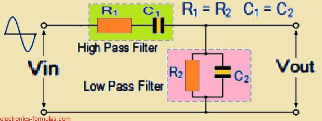
The RC network in that diagram is actually made from two simple parts put together, one is a series RC circuit and the other is a parallel RC circuit.
When you connect them like this, then what you end up with is a High Pass Filter sitting with a Low Pass Filter, one lets the higher frequencies through, the other lets the lower ones through, that is the basic idea.
Now because both are working together, the circuit does not pass everything, it only allows a small window of frequencies to come out properly, so it behaves like a second-order Band Pass Filter, quite selective.
Meaning it focuses only on a specific range, not wide, and this sharp focus is what people call a high Q factor, it locks onto a narrow band around the resonant frequency fr.
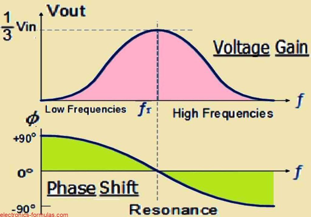
If you think about low frequencies first, the series capacitor C1 has very high reactance there, so it almost behaves like an open circuit, the signal does not really get through, and because of that the output Vout is nearly nothing.
Then if you go to the other side, at high frequencies, the parallel capacitor C2 shows very low reactance.
It starts behaving like a short circuit across the output, so again the signal dies out and Vout becomes very small.
So naturally, somewhere in between these two ends, there has to be a point where C1 is no longer acting open and C2 is no longer acting like a short, and right there the output suddenly rises, that point is where Vout hits its peak, and that frequency is what we call fr.
At this resonant frequency, something interesting happens, the reactance of the circuit matches the resistance, so Xc = R.
And because of that the phase difference between input and output drops to zero degrees, both signals line up, and at this exact point the output voltage reaches its maximum value, which comes out to be one-third, 1/3, of the input voltage.
Analyzing Oscillator Output Gain and Phase Shift
Phase Angle Behavior In RC Network
So now, when the frequency is very low, then the phase angle, that difference between the input and the output signals, it turns positive. This simply means the output signal starts moving ahead of the input in time, it reaches earlier, and we call that Phase Advanced condition.
But when the frequency goes very high, then things flip around, the phase angle becomes negative, which tells us that the output signal is now falling behind the input signal in timing, and that situation is called Phase Delay condition.
Resonant Frequency Alignment
Now, in between the low frequency side and the high frequency side, there comes one particular point, and at that point the circuit hits its resonant frequency fr, and right there something lines up, the input signal and the output signal, they fall together.
At that moment there is no phase difference left, the phase angle goes to 0 degree, nothing is leading or lagging, both just move together. We call that condition "in-phase", because the signals are basically walking side by side.
Wien Bridge Oscillator Frequency Formula
Therefore, we describe this resonant frequency fr using the formula fr = 1/(2πRC).
Here fr is the Resonant Frequency in Hertz and R is the Resistance in Ohms and C is the Capacitance in Farads.
Why Output Must Be One Third
Like we talked earlier, when the output voltage Vout of the RC network slowly reaches one third of the input voltage Vin, then at that point the output hits its maximum, and only then the circuit is able to oscillate, that exact condition matters.
But then the question comes, why one third only, why not some other value. So we first look into the RC circuit complex impedance which we normally write as Z = R ± jX, where R is resistance and X is reactance, that is where the reasoning starts.
Complex Impedance Reasoning
From our earlier AC Theory we know that this complex impedance has two parts where the real part R is resistance and the imaginary part X is reactance. And here because we are using capacitors the reactance part is basically the capacitive reactance Xc.
Interaction Of The Two RC Sections
If we want to understand fully why the output of the RC network must be one third or 0.333 times the input voltage then we have to think about how both these RC circuits are connected together and how their complex impedances work against each other and interact. Only then we realize that this special division of voltage allows the oscillation to happen in the most stable way.
Analyzing the RC Network
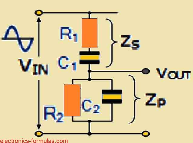
Now we draw that RC network once again and we see that it is basically made up of two coupled RC circuits and the output comes from that junction point where the RC parts meet. So the lower branch is a parallel branch that has R2 and C2 together and the upper branch is a series branch that has R1 and C1 together. So now we understand the whole shape like that.
Series And Parallel Impedance Meaning
So now we say that ZS can be used to show the total DC impedance of the upper series branch that is made using R1 and C1. And ZP will show the total impedance of that lower parallel branch that is made using R2 and C2. And since both ZS and ZP are in series across the input voltage VIN then they act like a voltage divider. So now the output voltage can be measured across ZP as we see in that figure.
Given Values For Calculation
Suppose we take R1 and R2 both as 10 kΩ and we take C1 and C2 both as 4.7 nF and we take the frequency f as 4 kHz. So now with these values we can start doing all the calculations in the following simple manner.
Series Impedance Calculation
Next we calculate the total impedance of the series branch made using R1 and C1. So we first take R = 8.5 kΩ but XC = 1/(2πfC).
We put the values and we get XC = 1/(2π * 4 * 4.7) = 8.5 kΩ.
Now ZS = √(R2 + XC2) = √(85002 + 85002) = 12020 Ω which is around 12 kΩ.
From the given data we see that at 4 kHz the capacitor reactance becomes equal to the resistor value of 8.5 kΩ and this makes the upper series impedance ZS equal to 12 kΩ.
Need To Analyze The Parallel Impedance
Next we look at the lower branch which is the parallel impedance ZP. Here the resistor and capacitor are in parallel and that combination influences the overall impedance strongly. So we have to carefully see how they combine so that we can get the correct resultant impedance of that parallel network.
Parallel Impedance Calculation
So the total impedance of the lower parallel branch that has R2 and C2 is given like this: R = 8.5 kΩ and XC = 8.5 kΩ.
Now 1/Z = 1/R + 1/XC = 1/8500 + 1/8500. So this gives Z = 4250 Ω or around 4.2 kΩ.
With the supply frequency still at 4000 Hz the total DC impedance of that parallel RC becomes 4.2 kΩ (R || XC).
But to get the parallel vector value we must do a vector addition and we write R = 4.2 kΩ and XC = 4.2 kΩ.
So ZP = √(R2 + XC2) = √(42002 + 42002). So we get ZP = 5940 Ω or around 6 kΩ.
Final Impedance Divider Result
We already have the vector value for ZS which is 12 kΩ and we already calculated the parallel vector impedance ZP which is 6 kΩ.
So it becomes easy for us to calculate the total output impedance of the divider at that frequency.
So Zout = ZP / (ZP + ZS) = 6 / (6 + 12) = 0.3333 or 1/3.
Output Voltage Condition
At the oscillation frequency we find clearly that the magnitude of Vout will be equal to Zout multiplied by Vin.
This becomes interesting because it shows that Vout actually becomes one-third of Vin.
This 1/3 behavior is a very important property of this frequency selective RC network and this property becomes crucial for the working of the Wien Bridge Oscillator.
Basic Wien Bridge Oscillator Formation
Now if we take this RC network and put it across a non-inverting op amp amplifier having a gain of 1 + R1/R2 then we actually create the basic core of a Wien Bridge Oscillator.
This combination of components and how they interact allows the oscillator to run smoothly and produce the intended stable sinewave output.
Understanding a Wien Bridge Oscillator Circuit
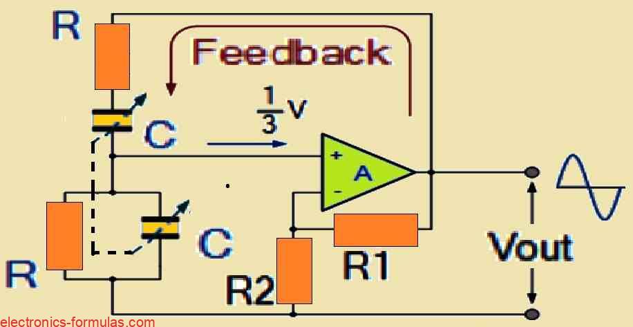
Here we see that in the above diagram we are taking the output signal from the op amp and we are feeding that same signal back to both the inputs.
One part of this feedback goes to the inverting input through the resistor divider that is made using R1 and R2, and this whole thing helps us to adjust the voltage gain of the amplifier inside some fixed limits by using negative feedback.
Positive Feedback By RC Wien Bridge Network
The other part of the feedback becomes more interesting because here we have resistors and capacitors making one network that moves to the non inverting input. This is the exact place where the positive feedback is created, and this is done by the RC Wien Bridge network. So this positive feedback is the main thing that starts the oscillation in the circuit.
Zero Phase Shift Condition Of RC Network
You may already know that when the RC network sits inside the positive feedback path then it shows zero phase shift at exactly one frequency and that special frequency is called the resonant frequency.
When this resonant frequency that we call fr is reached then the voltages on the inverting input and the non inverting input become exactly equal and they also become perfectly in phase.
Now at that instant the positive feedback cancels the negative feedback, and the oscillation starts growing at the circuit output.
Minimum Gain Requirement For Oscillation
For the oscillations to begin we have to make sure that the voltage gain of the circuit becomes at least three because the input becomes one third of the output.
So this gain condition Av ≥ 3 is set by the feedback resistors R1 and R2, and we can calculate this using the non inverting amplifier gain formula 1 + (R1/R2).
Op Amp High Frequency Limitation
We also remember that normal operational amplifiers have limits on the open loop gain, so if you want to design for frequencies above 1 MHz then you have to use a high frequency op amp or a special fast op amp so that the oscillator can work correctly.
Wien Bridge Oscillator Problem Number 1
So we have a Wien Bridge Oscillator circuit where the resistor is 12 kΩ and the capacitor is adjustable from 1 nF to 600 nF, and we want to find the maximum and minimum oscillation frequency of the circuit.
We already know that the oscillation frequency for the Wien Bridge Oscillator can be written as fr = 1 / (2 * π * R * C).
So the minimum frequency becomes fmin = 1/(2 * π * 12000 * 600 * 10-9) = 22 Hz.
And the maximum frequency becomes fmax = 1/(2 * π * 12000 * 1 * 10-9) = 13263 Hz.
Wien Bridge Oscillator Problem Number 2
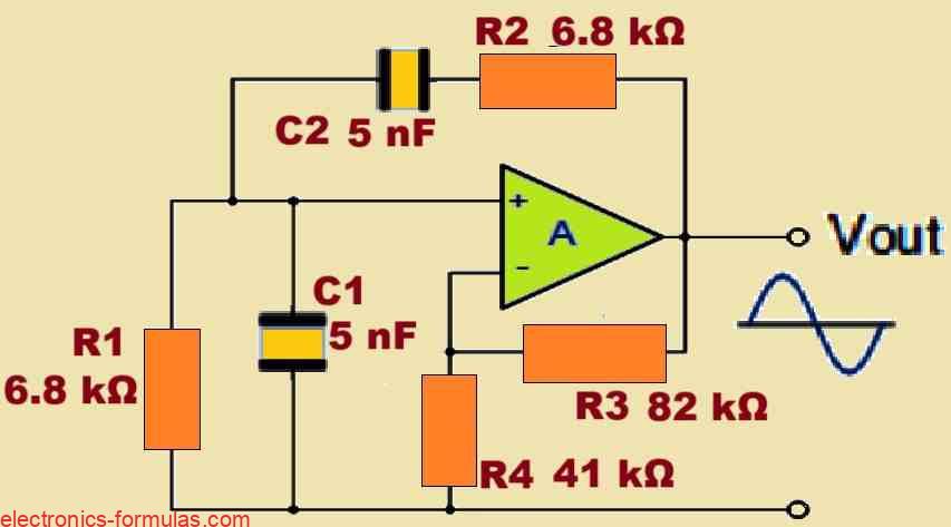
Next suppose we have one more Wien Bridge Oscillator circuit and we want an output sinusoidal frequency of 4700 Hertz or 4.7 kHz. So now we want to calculate the values of R1, R2, C1, and C2 which are the parts that decide the oscillation frequency.
Since we are assuming that the oscillator is based on a non inverting operational amplifier then we will also calculate the minimum gain resistors that help to maintain the right oscillation amplitude. Finally we will also draw the circuit with the calculated values.
We begin with the same formula fr = 1 / (2 * π * R * C) = 4700.
Now we already know that in this configuration we have R1 = R2 and C1 = C2. So now if we choose the feedback capacitors to be 5 nF then the value of the feedback resistors becomes like this:
fr = 1/(2 * π * R * C)
So R = 1/(2 * π * fr * C)
= 1/(2 * π * 4700 * 5 * 10-3)
= 6772.55 Ω which we can take as 6.8 kΩ.
Setting Gain Resistors For Oscillation Start
If we actually want the sinusoidal oscillation to start properly, we have to make sure the voltage gain is at least 3, Av ≥ 3, that part cannot be lower. In a non inverting op amp setup this gain does not come by magic, it is fixed by R3 and R4, and we normally write it as AV = 1 + R3/R4, which needs to reach 3 or a bit more.
Now say we pick R3 as 82 kΩ, just a practical value, then R4 comes straight from the same relation, 1 + R3/R4 = 3. Solving that gives R4 = R3/(3 - 1), which is R3/2, so 82 divided by 2, around 41 kΩ, simple enough.
But in real life it does not behave as neatly as theory, so even though gain 3 is enough on paper, usually we need a little push, something like 3.1, just to make sure oscillation actually starts. If you recalculate R4 using a gain of 3.1, the value shifts slightly and comes close to 39 kΩ.
With those values in hand, nothing more to juggle, we can finally draw the complete Wien Bridge Oscillator circuit, exactly as shown below.
Wien Bridge Oscillator Circuit Diagram with Calculated Part Values
Conclusions
when we try to understand how oscillations are created in a Wien Bridge Oscillator circuit, the first thing that comes up is this, some conditions have to be right, they cannot be half done, they must be fully satisfied while designing it, otherwise nothing really works.
Even when there is no input signal at all, the Wien Bridge Oscillator still has to make its own continuous output oscillation. It should start by itself and keep going, and this natural behavior matters a lot, because that is what keeps the oscillation alive and running instead of stopping after a moment.
Flexibility Of Frequency
We also see that the Wien Bridge Oscillator is very flexible for frequency making because it can generate a wide range of frequencies that can be used for many types of applications and so this makes the circuit very useful.
Required Amplifier Gain Condition
Another very important condition is that the voltage gain of the amplifier inside the circuit must be more than 3 and so this requirement is needed because that allows the system to maintain and sustain the oscillatory action.
RC Network And Phase Shift
We also see that the RC network that works together with this oscillator can work nicely with a non inverting amplifier design and this type of connection gives the required phase shift that is necessary for keeping the oscillation alive continuously.
Input Resistance Requirement
Another point says that the input resistance of the amplifier must be much higher than the circuit resistance R and this ensures that the amplifier will not disturb the RC network and will not spoil the required working characteristics.
Output Resistance Must Stay Low
We also have to note that the output resistance of the amplifier must be kept low because this helps to reduce the effects of external loading which otherwise can destroy the stability of the oscillations and make the waveform weak or unstable.
Proper Amplitude Control
Another concern comes up here, we need something in place to control the amplitude of the oscillations. Because if the amplifier gain goes too low, then the oscillation does not stay alive, it slowly drops down and after some time it just stops.
But if the gain goes too high, then the output gets pushed close to the saturation levels, which are limited by the supply rails, and when that happens the waveform does not stay clean anymore, it starts getting distorted, so that balance part matters.
Amplitude Stabilizing Components
So to make sure the Wien Bridge Oscillator keeps oscillating continuously, we usually add some amplitude stabilizing method inside the circuit.
Because without that it can drift or stop.
One simple way is putting feedback diodes in the loop, and these parts help in holding the oscillatory output at a safe level, so it keeps oscillating endlessly without creating problems or running out of control.
References: Wien bridge oscillator
Leave a Reply