• Skip to main content
  • Skip to primary sidebar

Making Easy Circuits

Learn and build electronic circuits

You are here: Home / Oscillators / Wien Bridge Oscillator with Single-Gang Pot

Wien Bridge Oscillator with Single-Gang Pot

Last Updated on March 8, 2021 by Admin Leave a Comment

The Wien bridge oscillator circuit generates a low-distortion sine wave of steady amplitude that ranges from 15 Hz to 150 kHz. It needs just four op-amps and can be powered from just a 9 V battery.

Moreover, this device is quite distinct compared to conventional Wien bridge oscillators because it does not necessitate a dual-gang potentiometer for tuning.

Circuit Description

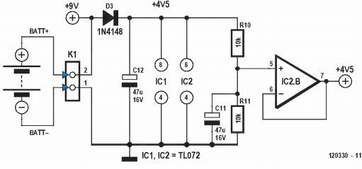
Op-amp IC2b delivers an artificial ground so that the circuit will function from a unipolar supply (the 9 V battery or a power pack). IC2a works as the main amplifier for the oscillator. The frequency range is split into four decades by a 2-pole, 4-way rotary switch, SW1.

wien bridge schematic compressed

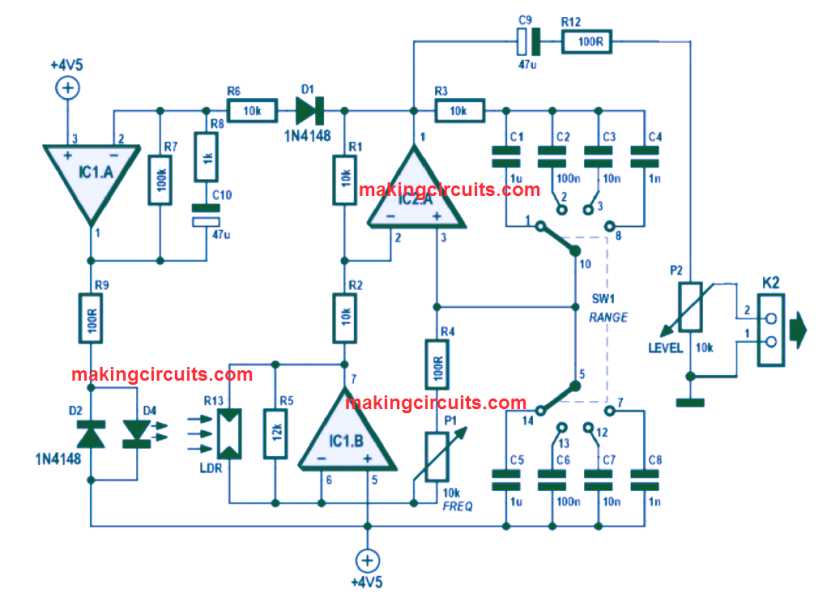
There can be only one arm in the Wien bridge network to have a different configuration. However, the change in the positive feedback that would typically happen is returned for by IC1b, hence bootstrapping R2.

As a result, the negative feedback will be modified just enough to sustain oscillation. A linear variation in the resistance of the tuning pot produces a coarse logarithmic change in frequency. If you need to obtain a more linear change, a log-taper pot must be included.

This action rotates the knob counterclockwise which boosts the frequency. Another possibility of using the anti-log pot is by turning it around but since these parts are difficult to find it’s best to stick with the suggested configuration.

IC1a works as an integrator that supervises the amplitude of the output signal and powers an LED (D2).

This part must be attached facing the LDR (Light Dependent Resistor) and protected from ambient light using materials like heat shrink tubes. Then, the IC would be able to regulate the gain of IC2a which warrants steady oscillation with very minimal distortion.

The peak output amplitude of the generator is around 2 Vp-p when the LED and LDR are fixed as close as possible.

Furthermore, distortion is greatly reduced (less than 0.5%) in the lowest range and quite low to measure at higher ranges. You may pick any LDR type as long as its dark resistance is more than 100 kΩ.

In case you do not possess such LDR, attempt to ramp up the resistance of R5 until the oscillation begins. This circuit was constructed on a breadboard as a prototype using dual and quad op-amp packages. Both performed well.

9 V to 4.5 V Converter for the above wien bridge oscillator circuit

Wien bridge oscillator

You'll also like:

  • 1.  Quartz Mosquito Repellent using a single IC4060
  • 2.  Understanding Phase shift Oscillator Circuit
  • 3.  Square Wave Generator Circuit with External ON/OFF Control
  • 4.  Simple Pulse Generator Circuit
  • 5.  Simple Multivibrator Circuit Projects – Astable, Bistable, Monostable
  • 6.  Low Voltage Crystal Oscillator Circuit

About Admin

Hey friends, Thanks a bunch for stopping by this site! I am an engineer with a Bachelor of Engineering in Electronics and Telecommunication. One of my passions is gathering information from all sorts of electronics books and tutorials. I then take that information and compile it into a language that is super easy to understand. My goal is to make those complex electronics circuit concepts and technical terms much more accessible for all the new and budding electronics engineers out there. I can also design customized circuit diagrams as required by the users.
If you have any questions related to this field, please do not hesitate to drop a comment! I am always here and ready to help you out with any queries you might have. I cannot wait to hear from you!

Reader Interactions

Leave a Reply Cancel reply

Your email address will not be published. Required fields are marked *

Primary Sidebar

Categories

  • 3 Phase (4)
  • 8051 Microcontroller (1)
  • Arduino (11)
  • Audio and Amplifier (102)
  • Automation (8)
  • Battery Chargers (64)
  • Bicycle Projects (4)
  • Car and Motorcycle Projects (39)
  • Datasheets (10)
  • DIY Projects (5)
  • Electrical (15)
  • Free Energy (6)
  • Games Projects (2)
  • High Voltage (14)
  • Hobby Projects (30)
  • Household Circuits (2)
  • IC 555 Circuits (5)
  • Ignition Circuits (2)
  • Indicators (50)
  • Infrared (6)
  • Inverter Circuits (29)
  • Lights and Lamps (97)
  • Medical (8)
  • Meter and Tester Circuits (38)
  • Motor Driver (17)
  • New Circuits (56)
  • Oscillators (30)
  • Pets and Pests (5)
  • Power supply (80)
  • Protection Circuits (25)
  • PWM (9)
  • Remote Control (20)
  • Security and Alarm Circuit (48)
  • Sensors and Detectors (66)
  • Signal Processor (23)
  • Solar Controller Circuits (62)
  • SSR (3)
  • Temperature Controller (20)
  • Timer (25)
  • Transformerless (7)
  • Transmitters (12)
  • Tutorials (45)
  • UPS (2)
  • Voltage Regulators (57)
  • Water Sensor and Controller (29)
  • Home
  • Privacy Policy
  • Contact
  • Disclaimer
  • Copyright

© 2025 · Making Easy Circuits