This article will attempt to describe the way to build a wireless cellphone battery charger circuit. With a wireless charger you can just get rid of the wires and charge your mobile from any location where the wireless signal resides.
Wired connections are always messy. The more electrical gadgets you have at your house, the more are the cables. However, with the coming of wireless technology the issue of wires / cables has reduced to a certain extent. This helps to reduce cluttering and keep the space clean. Wireless technology has walked a long way and there are various attempts to reduce the concept of wired connections.
How it works?
Before we delve onto the building of the the wireless cellphone wireless charger circuit, let us first try to see the principle behind the operation of the circuit. A wireless mobile battery charger circuit is based on the theory of mutual inductance. Based upon the theory of inductive coupling the power gets transferred to the receives on a wireless form. Inductance comes in two different type: Mutual InductanceandSelf Inductance.
In mutual inductance the conductor that carries the current is strategically positioned near to another conductor so as to pass the voltage to other conductor, and this is possible simply because of the presence of induced magnetic flux. The magnetic flux induced is further connected to another conductor, and the flux helps to induce the voltage to the second conductor. This principle of connecting conductors and induce of voltage among them is referred as inductively coupled.
Building the Circuit
The following images illustrates the circuit design of the proposed circuit:
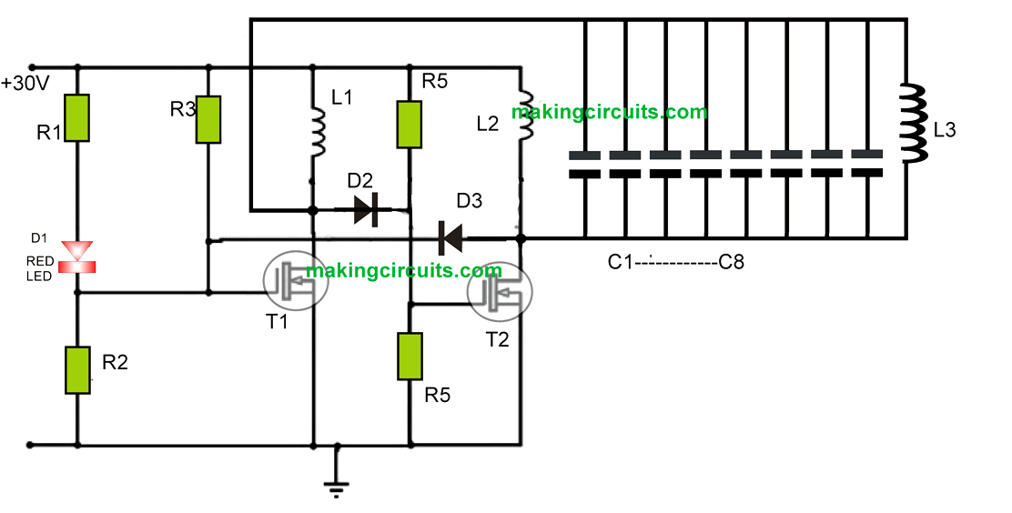
Transmitter Circuit
R1 = 1K
R2, R4 = 10K
R3, R5 = 100
D2, D3 = 1N4148
C1---C8 = 6.8nF
MOSFETS = IRF540
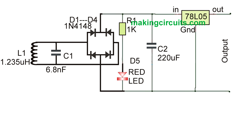
Receiver Circuit
As per diagram, there are two circuits that are used to develop the wireless battery charger. The first one is the transmitter circuit and is used to generate voltage on wireless fashion. This circuit has oscillator circuit, transmitter coil and DC power source. The oscillator circuit has two n channel MOSFETS – 4148 diodes and IRF 540. As the DC power flows to the oscillator, the current flows via the coils L1 and L2, and further drains the transistor’s terminal. Also at the same moment the voltage is found also in the transistors gate terminal. It is important to note that one transistor lies in OFF state while the other remain ON. Therefore, as the voltage releases from the OFF state transistor gets raised up, it further falls via the tank circuit, which is made of 0.674 transmitter coil and capacitors 6.8nf. One way to measure the operating frequency is by applying a formula - F=1/[2π√(LC)]
The second circuit, which acts as a receiving circuit is made of rectifier circuit, regulator and receiver coil. Now, when placing the receiving circuit near to the inductor, the AC power gets inducted, and is further set by the rectifier circuit, regulating on 5V DC with the help of the 7805 regulator. The rectifier circuit has 6.8nf capacitor and diode 1n4007. The regulator’s output has its connection to the battery.
Operating the system
In order to operate the wireless cellphone charger circuit, you first need to build the circuit as shown in Figure 1.0, and then turn on the power supply. Next you need to connect the battery charger at the circuit’s output point. Position the receiver coil near to the transmitter coil, and this will initiate charging the battery.
Wireless mobile charger is very useful as you can now have the luxury to charge the phone from anywhere. You can also charge camera batteries and Bluetooth headset. A little bit of modification into the proposed system, you can apply it to charge car battery. However, on the flip side power gets wasted to certain degree because of the mutual induction, and the design is meant only to cover a short distance. If you plan to cover a long distance you need to increase the inductor.
Impossible to work. Why this is published?
Some reasons and questions:
* R3, 100ohm drives all the time FET T1 gate. FET will burn immediately.
There is nothing to turn it off state.
* R3, 100 ohm bypass LED circuit. LED is always dark.
* R5, 100ohm drives all the time FET T2 gate. Gate has half battery voltage, 15V always. FET will burn.
* Power dissipation of resistors R5 is over 2W each. They will burn too.
* There is nothing understandable connections between coils to make circuit as bistable oscillotor.
* What is walue of L3?
* How are coils connected together?
I wonder who is the first designer to show this kind circuitry. There is many other publications just like this.
This was taken from one of the most popular sites https://www.electronicshub.org/wireless-mobile-battery-charger-circuit/
By the way if you could not make some circuits work that does not mean all those circuits are bad….
correction: This was taken from one of the most popular sites electronicshub(dot)org
Need it
get it 🙂