The article clearly shows an effective wireless LED brake light circuit which is often connected to a biker's helmet. The LEDs linked to the helmet circuit lights up as a reaction the motorcycle braking producing a superior brake light impact from the user's helmet.

The suggested helmet brake light circuit could possibly be conveniently executed by utilizing an affordable homemade FM transmitter and a small FM transistor radio.
A compact FM transmitter can be viewed in the following diagram which turns into the brake light transmitter circuit for the helmet LEDs.
![]()
The above design shows a basic FM transmitter circuit which can be built-in with the brake light voltage signal of the motorcycle, or just across the brake light lamp connection
The circuit produces an FM signal over the standard FM band of 80 to 108 MHz. Hence the transmitted signals turn out to be receivable over any ordinary FM radio positioned within a radial distance of 30 meters.The coil would require tweaking for set up the precise point of reception over an FM radio
The mentioned 12V lines need to be linked straight across the brake light lamp of the bike.
The BC547 on the right together with its base zener makes certain that the FM transmitter circuit obtains the designated 3 V for the operations.
The UM66 IC is a musical chip which allows the circuit to produce an AF modulated FM transmission making sure much more powerful and robust FM signals compared to a transmitter without having audio modulation stage.
Consequently every time brakes are utilized, the transmitter is turned on and directs a powerful audio modulated FM signal for the FM radio placed inside the helmet.
The FM Radio as the Receiver

Any compact FM radio could be utilized when considering for obtaining the transmitted signals from the above described FM transmitter. An illustration circuit of a small FM radio may be observed below:
In the image you can easily observe a speaker related to the radio and also a 9 V battery as the supply source.
Both of the previously listed attachments ought to be taken off the kit and ought to become something as provided below after the recommended changes:
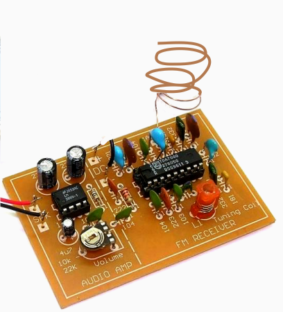
So that you can produce the above radio suitable for a LEd driver stage and for illuminating a couple of LEDs in accordance with the obtained FM transmitter signals, we will need to create some fascinating electrical alterations with the demonstrated FM radio kit.
The following figure demonstrates precisely how a small electrical stage consisting a BJT and inductor can be utilized for changing the amplified audio from the radio into a DC which might then light up a pair of LEds brightly each and every time the brakes are used in the motor bike.
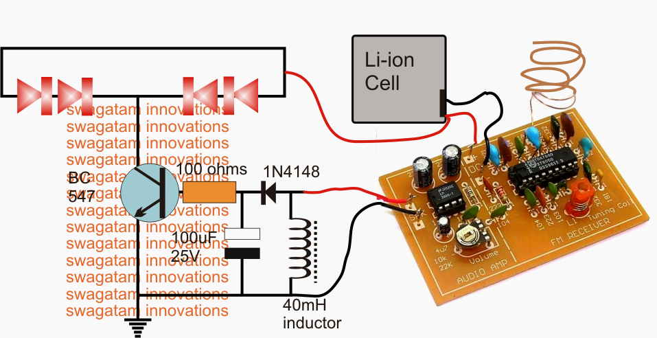
In the above diagram we observe the speaker terminals of the FM radio being joined with an inductor and the output across the inductor further associated with a diode, capacitor rectifier stage for transforming into a sturdy DC base drive for the following BC547 LED driver stage.
We are able to also observe the 9 V battery being changed to a 3.7 V Li-ion cell to be able to create the design compact and quite easily inclosable inside the helmet.
When the radio starts acquiring the switched audio, the weak audio frequency across the speaker wires turn out to be focused and stimulated with the aid of the attached inductor, this improved voltage is fixed and filtered by the diode capacitor network to ensure that the BC547 has the capacity to obtain a clean DC conversion for driving the set of LEds situated over the helmet body.
Now at any time the brakes are employed the signal from the transmitter is acquired by the FM radio inside the helmet leading to the necessary illumination of the LED strip by means of the operations as spelled out in the above section.
Tips on how to start up the offered LED helmet brake light circuit
Before setting up the Rx LED module over the helmet, the radio board ought to be set properly as per the following justification:
Turn On the FM radio without any antenna associated and the station selection on the radio being on any random situation.
You can definitely find the LEDs glowing in this scenario, now adjust the volume manage preset in the amplifier section of the FM board very gradually unless you find the LED just prevents illuminating.
After the above setting remove the speaker output wires from the LED driver stage and let a speaker be linked with these wires. Additionally hook up the antenna wire back in the demonstrated position.
Activate the transmitter unit and adjust the red colored frequency coil or it may be a capacitor trimmer in other variants of FM receivers, tune it carefully until a clean and powerful musical audio (UM66 music) is identified in the speaker. Seal the tuning device with glue.
Now take away the speaker and attach the wires back with the LEd driver stage.
Activate the transmitter and you'll find the LEDs glowing brightly as a reaction to the acquired musical transmission from the Tx unit. Switching of the Tx circuit ought to turn off the LEDs at the same time immediately verifying the ideal functioning of the process.
Verify the reply just a few more times after which you might continue with the last installations.
Leave a Reply