In this post we learn how to illuminate a small DC lamp remotely through RF disturbances created by switching a battery, motor circuit some 4 meters away. This distance can be increased suitably by tweaking the circuit settings.
Marconi's Wireless Transmitter
Most people understand from their practical experience of radio disturbance that an electric spark produces high frequency. The initial wireless transmitters more than A century ago (Marconi 1895) utilized a spark gap using a dipole antenna. The frequency was in the VHF range and had been modified by the length of the antenna. The receiver must have been a second dipole and a fritter. The Fritter was something similar to a characterized loose contact manufactured from metallic chips. The received RF pulse could shut the contact.
Possibly other folks have previously noticed these: Old radios frequently have problems with the tuning switch, for the reason that contacts oxidize. At some stage you can't pick up anything at all anymore. Normally a aimed whack using the edge of the hand, then simply it will go again. However occasionally an electrical spark results in success. You actually listen to a crack (the next door neighbor switches off the light), after which the radio shuts off again. Therefore the loose contact within the radio functions just like a fritter.
Just lately, I happened to look at just as a flip-flop turned over in an electronic circuit exactly where an oscilloscope was at the moment hanging. That's when the concept was developed: Exactly what Uropa's unstable contact (known as the Fritter) performed, but that's just what a transistor flip-flop should do. Hence be able to function! The foundation was an electronics kit. And here is the end result:
Wireless Lamp Circuit using RF Disturbance Triggering
The circuit diagram displays a monostable multivibrator. In regards to the potentiometer, it is used for the the bias and may be tweaked to ensure that the NPN simply doesn't saturate, enabling it to be at a touch-and-go situation.
The antenna in the base of the first transistor receives an RF pulse that activates the flip-flop. Now the lamp illuminates for a second after which it switches off again. Then the circuit uses a couple of seconds to arrange to receive all over again.
Experiment with this! Really, with the light switch the receiver could be activated. The sensitivity can be improved extremely skillfully. However at some time the circuit begins by itself. Then you certainly have no idea: Had been it the neighbor?

And after this next, the associated transmitter can be built. The simplest way is by using a little DC motor. It usually troubles me anyway. You simply ought to hook up one antenna. It does not require to be a dipole, just one wire is effective.
The antennas on the transmitter and the receiver needs to be the exact same length. Each were 50 cm long in the prototype. Therefore the wavelength was 2 m (the radio amateurs in the 2-meter band pardon me), the frequency about 150 MHz.
And right now you most likely all wish to know how large the product range ended up being. Very pleased four meters! Very well, Marconi's radio transmitter continued. But he undoubtedly got wider sparks.
Within the very best times during the the radio transmitters, 1000s of kilometers had been spanned by longwave. The transmitters had massive pulse outputs of numerous megawatts. The brief impulses focused the efficiency as well as resulted in really huge bandwidths. Virtually just one transmitter might are employed at a period of time. For this reason the procedure ran out of fashion once again.
Activating a Remote Speaker with a Spark
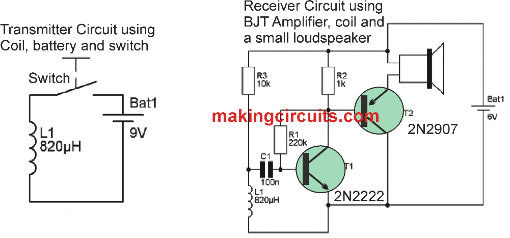
We saw in the above experiment how a bulb can ignited wirelessly by igniting a momentary spark some distance away using a motor, battery and a switch. In the following experiment we will learn how the same can e done to create a big crackling sound on a speaker using a small BJT amplifier circuit, and a small RF generator circuit.

In this experiment the transmitter is held at a distance of about 5 meters, and each time the switch is momentarily depressed, the RF noise is received by the inductor L1 within the receiver circuit, creating a large crackling RF disturbance sound on the speaker.
This happens because the momentary switching of transmitter coil causes a pulse to be generated which is transmitted in the air.
This RF noise hits the inductor of the receiver circuit, and induces an identical pulse voltage at the base of the NPN BJT, which is amplified by this NPN. The PNP makes sure that the amplified signal from the NPN is further amplified sufficiently to make the loudspeaker burst into a noisy output having a frequency and waveform exactly equal to the transmitters pulse output.
Leave a Reply