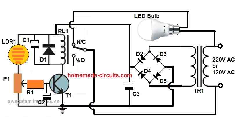
Just a single transistor, an LDR, a few resistors, and a relay could all be used to create a somewhat useful automated street light, as seen in the diagram below.
Parts List
| Component | Value / Specification |
|---|---|
| Resistors | All are 1/4 watt, 5% CFR |
| R1 | 1K ohm |
| P1 | 10K preset |
| LDR | Any standard LDR |
| Capacitors | |
| C1 | 220µF / 25V Electrolytic |
| C2 | 10µF / 25V Electrolytic |
| C3 | 1000µF / 25V Electrolytic |
| Diodes | |
| D1 – D5 | 1N4007 |
| Transistor | |
| T1 | BC547 |
| Transformer | |
| TR1 | 0-12V / 500mA or 1A |
| Relay | |
| RL1 | 12V, 200–400 ohm coil resistance |
| LED Bulb | |
| - | 220V / 120V, 100W or as required for street light |
How the Circuit Works
The working of this circuit is quite straightforward but let us go step by step, right? Now during the daytime when the surrounding light is quite strong, then the LDR is going to have a very low resistance.
Because of this, the transistor base gets more pushed towards the positive potential which means the base voltage is now at the needed 0.6V, ok? Since this is enough to keep the transistor in conduction mode, then the transistor stays switched ON.
Now when the transistor is ON, then the relay also remains in the activated state which means its internal contacts stay positioned at the normally open (N/O) side.
But since the lamp is wired up at the normally closed (N/C) contact of the relay, then the lamp is going to remain switched OFF at this moment, right?
But then as evening time comes and the surrounding light starts dropping, then the LDR’s resistance slowly starts increasing.
Eventually when it increases to a high enough level then the base drive of the transistor starts getting weaker because the base potential is now raised towards ground through P1.
This action basically stops the transistor from getting biased, ok?
Now because of this, the transistor turns OFF. The moment the transistor turns OFF then its collector side stops conducting and this instantly deactivates the relay.
The relay contacts now flip from the normally open (N/O) side to the normally closed (N/C) side. The lamp is connected at this N/C contact, so now the current gets a path to pass through the lamp and then the lamp turns ON instantly, right?
Then the next morning when daylight starts increasing again then the LDR resistance again drops down, the transistor gets back its bias and switches ON again which causes the relay to activate once more.
The relay contacts flip back to the normally open (N/O) position, breaking the current to the lamp and then the lamp switches OFF. This whole process keeps repeating automatically every day.
But now, what about those transition periods, like twilight, when the light is neither too high nor too low? If we do not do anything then the relay could start chattering and fluctuating which is bad, right?
To stop this we have added capacitors across the transistor base and the relay. These capacitors ensure that the relay does not chatter but instead changes its position smoothly.
And what if we want to set the light level at which the relay should switch ON and OFF? Then that is where the potentiometer or preset comes in. By adjusting it properly we can fix the exact light threshold where the relay will operate.
But remember one very important thing—when installing this street light circuit then we must ensure that the lamp’s light does not fall directly on the LDR. If that happens then the LDR will keep switching between low and high resistance rapidly, making the relay and lamp oscillate continuously which is not what we want, ok?
Setting Up the Circuit:
First set the preset wiper to the ground level.
Now switch ON the power supply.
Next illuminate the LDR or the surrounding area with the amount of light at which you want the relay to change state.
Slowly rotate the P1 preset until the relay just activates.
Once done seal the preset with quick-fix glue so it does not shift later.
That is it! Your circuit is ready.
Now time for testing! Just cover the LDR with something opaque and then you will immediately see the lamp turning ON. Remove the cover and then the lamp will switch OFF instantly. This confirms everything is working perfectly…
Construction Tips
Ok now, let us build the circuit step by step, Because if we do not do it properly then the circuit may not work or worse, it may get damaged which we do not want, right? So, here is how we do it.
Step 1: Picking the Right Parts
First we need to get an LDR that can change resistance properly. When it is bright then its resistance must go below 1K ohms and when it is dark then it must go over 100K ohms otherwise the circuit will not work right.
The transistor T1 should be a normal NPN type like BC547 but if the relay takes more current then we must use something stronger like BC337 or 2N2222.
The relay voltage must match the power supply. If we are using 12V then the relay should be 12V, not more, not less, ok? Also its contact rating must be higher than the LED bulb’s current otherwise, it will burn out.
The diodes D2, D3, D4, D5 form the bridge rectifier and these must be strong enough. If the LED bulb is 10W then at least 1A diodes must be used, like 1N4007, or else they will heat up.
The capacitor C3 must be around 1000µF/25V so that the relay does not keep clicking on and off randomly.
The diode D1 which is across the relay coil must be 1N4007 and this is very important, because if we do not use it then the transistor will get damaged from back EMF.
Step 2: Putting the Parts Together on a Board
First we must decide whether to use a PCB or a general-purpose board. If we want a strong circuit then PCB is better but if we just want to test then Veroboard is ok.
We must place the parts close to each other because if the wires are too long, then the circuit may behave weirdly.
The LDR must be placed in such a way that it gets sunlight properly but we must make sure that the LED bulb’s light does not fall on it otherwise the circuit will start flickering on and off nonstop, and that will be a big problem, right?
Step 3: Wiring Everything
First we should connect the small parts like the LDR, P1, R1, C1, C2, and the transistor T1.
Then we should connect the relay coil carefully making sure that D1 is placed correctly across it.
Next we must wire the transformer and bridge rectifier. The AC input goes to the transformer primary, and its secondary is connected to the rectifier diodes.
The rectifier output is then filtered by capacitor C3 and this voltage goes to the relay’s common terminal.
The LED bulb is connected to the N/C contact of the relay, because we want it to be ON when the relay is OFF. If we connect it wrong then it will work the opposite way, which is not what we want, right?
Step 4: Testing and Fixing Issues
First we must double-check all connections with a multimeter because if there is a short circuit then things will start burning when we switch it ON which is bad.
Then we should switch ON the power and see what happens. In daytime the relay must be ON and the LED bulb must be OFF.
Next we should cover the LDR with a dark cloth or hand. The relay must now turn OFF and the LED bulb must turn ON.
If the relay is clicking fast or not working properly then the capacitor C3 might be missing or faulty.
If the LED bulb does not turn ON then maybe the relay wiring or the transformer wiring is wrong so we must check it again.
Step 5: Installing the Circuit
If everything is working fine then we must solder all the wires properly and mount the circuit inside a safe box.
The LDR must be installed in an open space where it can sense the real sunlight, but we must make sure the bulb’s light does not reach it directly because if that happens then the relay will keep switching ON and OFF like crazy.
The circuit must be placed in a dry and safe area because if water enters then things will short-circuit and the whole thing will stop working.
Ok so if we do everything as mentioned then this circuit will work perfectly without any problems. It will turn ON the LED bulb at night and switch it OFF in the morning all by itself, without us having to do anything!
Leave a Reply