• Skip to main content
  • Skip to primary sidebar

Making Easy Circuits

Learn and build electronic circuits

You are here: Home / New Circuits / How to Build a LM317 as a Variable Voltage Regulator and Variable Current Regulator

How to Build a LM317 as a Variable Voltage Regulator and Variable Current Regulator

Last Updated on February 17, 2018 by Admin Leave a Comment

The submit demonstrates precisely how the convenient IC LM317/338/396 can be utilized as a changeable voltage regulator as well as as a variable current regulator by means of simple configurations, employed for driving particular laser diodes which can be proven to possess strict working specs, and might be driven only by way of specific driver circuits. The mentioned LM317 design is so precise that it might be preferably appropriate for all such specialist current and voltage controlled applications.
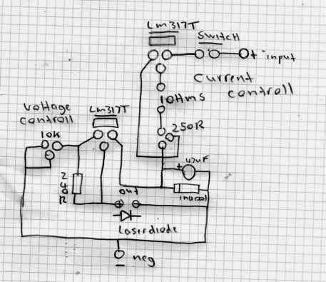
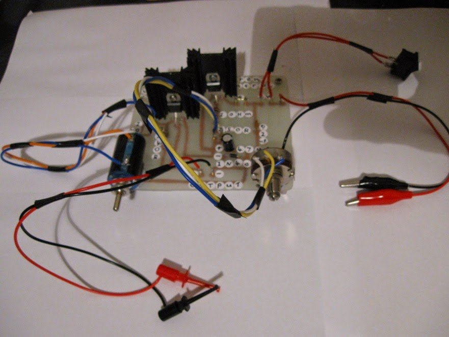
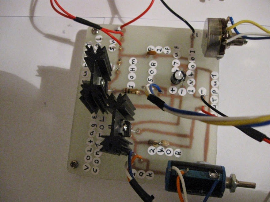
Talking about the presented circuit diagram, the set up appears quite simple, two LM317 IC s can be viewed, one set up in its standard voltage regulator mode and the other in a current control mode.

steven 1
To be accurate the upper LM317 forms the variable current regulator stage while the lower behaves like a variable voltage controller stage.
The input supply source is linked across the Vin and ground of the upper current regulator circuit, the output out of this stage goes to the input of the lower LM317 variable voltage regulator stage. Fundamentally both the phases are attached in series for applying a total quick and easy voltage and current regulation for the linked load which can be a laser diode in the present case.
R2 is chosen to obtain a range of around 1.25A max current limit, the minimum permitted being 5mA when the full 250 ohms is placed in the path, which means the current to the laser might be set as preferred, somewhere between 5mA to 1 amp.
The above is determined by utilizing the following formula:
R = 1.25/max allowed current
The current managed voltage provided from the upper stage is next placed on the lower LM317 voltage regulator circuit, which allows the most wanted voltage to be set between 1.25V to 30V, here the max range getting 9V since the source is a 9V battery. This really is accomplished by adjusting R4.
The talked about circuit is allocated to handle not a lot more than 1.5amps, if higher current is needed, both the ICs could be replaced with LM338 for getting a max 5amp current or LM396 for a max of 10amp current.

currentcontrollvoltagecontrolldriverforlaserdiodes

2ndlaserdriverpowersupply001

2ndlaserdriverpowersupply002


2ndlaserdriverpowersupply003

2ndlaserdriverpowersupply004


2ndlaserdriverpowersupply005

2ndlaserdriverpowersupply009

You'll also like:

  • 1.  220V Fan Regulator Circuit
  • 2.  Simple Low Voltage Cut OFF Circuit
  • 3.  Designing a IC 723 Power Supply with Variable Voltage and Current
  • 4.  Solid-State ELCB Circuit using SCR and Triac
  • 5.  5V, 12V Buck Converter Circuit SMPS 220V
  • 6.  How to Build a Wireless Home theater Circuit using Bluetooth Headset

About Admin

Hey friends, Thanks a bunch for stopping by this site! I am an engineer with a Bachelor of Engineering in Electronics and Telecommunication. One of my passions is gathering information from all sorts of electronics books and tutorials. I then take that information and compile it into a language that is super easy to understand. My goal is to make those complex electronics circuit concepts and technical terms much more accessible for all the new and budding electronics engineers out there. I can also design customized circuit diagrams as required by the users.
If you have any questions related to this field, please do not hesitate to drop a comment! I am always here and ready to help you out with any queries you might have. I cannot wait to hear from you!

Reader Interactions

Leave a Reply Cancel reply

Your email address will not be published. Required fields are marked *

Primary Sidebar

Categories

  • 3 Phase (4)
  • 8051 Microcontroller (1)
  • Arduino (11)
  • Audio and Amplifier (102)
  • Automation (8)
  • Battery Chargers (64)
  • Bicycle Projects (4)
  • Car and Motorcycle Projects (39)
  • Datasheets (10)
  • DIY Projects (5)
  • Electrical (15)
  • Free Energy (6)
  • Games Projects (2)
  • High Voltage (14)
  • Hobby Projects (30)
  • Household Circuits (2)
  • IC 555 Circuits (5)
  • Ignition Circuits (2)
  • Indicators (50)
  • Infrared (6)
  • Inverter Circuits (29)
  • Lights and Lamps (97)
  • Medical (8)
  • Meter and Tester Circuits (38)
  • Motor Driver (17)
  • New Circuits (56)
  • Oscillators (30)
  • Pets and Pests (5)
  • Power supply (80)
  • Protection Circuits (25)
  • PWM (9)
  • Remote Control (20)
  • Security and Alarm Circuit (48)
  • Sensors and Detectors (66)
  • Signal Processor (23)
  • Solar Controller Circuits (62)
  • SSR (3)
  • Temperature Controller (20)
  • Timer (25)
  • Transformerless (7)
  • Transmitters (12)
  • Tutorials (45)
  • UPS (2)
  • Voltage Regulators (57)
  • Water Sensor and Controller (29)
  • Home
  • Privacy Policy
  • Contact
  • Disclaimer
  • Copyright

© 2025 · Making Easy Circuits