We Made This Simple Transformerless Power Supply with MOSFET, That Gives 0 to 300V DC and Adjustable Current, But Careful... It is Super Dangerous to touch in uncovered condition....
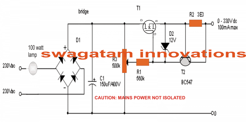
So here what we done is, we built one very easy and simple transformerless power supply circuit using just few parts and we used MOSFET as the main control device. That output from this circuit can be changed smoothly from 0V to around 300V DC, or even 330V if we want, and current can also be adjusted from around 100mA up to full 1 Amp. So this thing is super useful when we are doing high voltage experiments and testing circuits that need variable high voltage supply.
Now why we made this? Because many times when we do some risky high voltage research works, those expensive circuits go fully burn and become smoke due to some small mistake. So to stop this problem, I created this safe version of power supply which can give variable high voltage DC but with full current control and short circuit protection.
But remember this very serious thing – this circuit is not isolated from AC mains, so full mains electricity is present inside all points of the circuit when it is ON. That means if anybody touches any part by mistake when it is connected to power, then that shock can be fully deadly. Yes, this circuit can kill.
So we must always be super careful and never touch anything once circuit is ON. Always do tests with one hand and keep other hand away, and also use proper rubber gloves and stand on dry wooden surface. Never try this if you are not confident about mains safety.
One good point – short circuit proof
That good part is, the output current is fully limited, so even if we short the output, then nothing will burn. Current will stay within around 100mA and that will keep everything safe.
WARNING: ALL PARTS OF THIS CIRCUIT ARE CONNECTED WITH DIRECT MAINS AC. SO THIS IS FULLY LETHAL IF TOUCHED WHEN POWER IS ON. THIS CAN KILL ANY PERSON INSTANTLY. SO ALWAYS USE EXTREME PRECAUTIONS AND DO NOT TRY IF YOU ARE NOT SURE.
Circuit Diagram
UPDATE:
We Made It Even More Simple – This One Uses Fewer Parts But Still Gives 0 to 300V DC
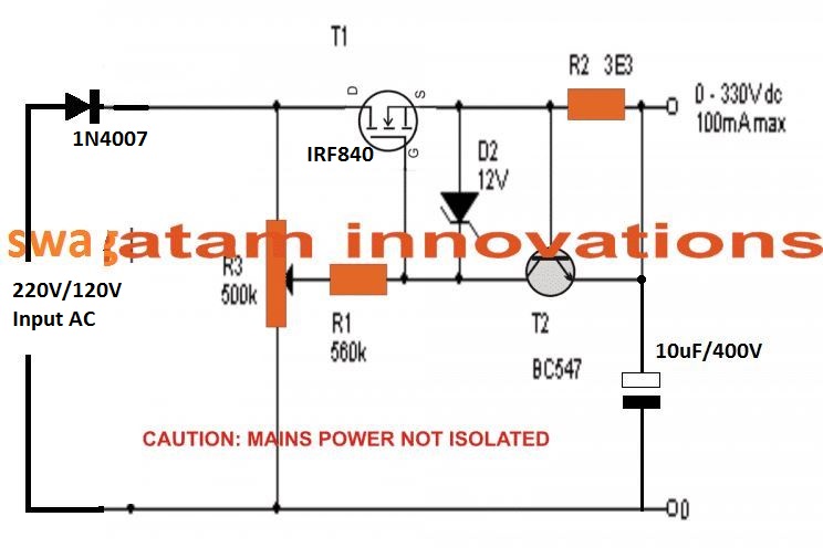
So that above circuit which we saw above was already easy and useful but now we can make it even more simple and clean by using this second version, which is shown in the below diagram.
Here what we did is, we removed the bridge rectifier part completely. That means no four diodes or bridge pack, just one single diode is enough now. By doing this, we reduced the load or stress on the MOSFET a lot. So now the MOSFET can work more relaxed and cool.
But wait there is a small downside also, now the rectification becomes half wave. That means the DC we get is having more ripple or more noise in it, since current flows only during one half of the AC cycle. So output is not very pure DC.
To reduce that ripple and make the DC a bit more smoother, we connected one capacitor of 10uF at the output side. That capacitor helps to fill the gaps between the pulses. If we want better quality DC with less ripple then we can increase that 10uF to 47uF or 100uF or more, depending on what we want.
What About Safety Bulb or Fuse?
Now in this version, we can still add that 100 watt bulb in series with input, like before. But here, it's kind of optional. Why? Because we already have that current limiter in the design – that part is still present and it protects the circuit from overload.
But still, if we want better protection then it is good idea to add one fuse also. So we can put a fuse in series with the input line, just before or after the on/off switch. That fuse will blow in case of serious fault and save everything else.
Load Should Be Less Than 100mA
Now one important thing – this power supply is not made for high current load. We must make sure that the output load does not take more than 100mA. That is the maximum safe current for this design. If we try to take more current, the circuit will either shut down or may get damaged.
This supply is good for small high-voltage testing circuits which need adjustable voltage from 0V up to 300V DC, but with small current.
Also one more thing to remember – all the transistors and MOSFETs used here should be mounted on proper aluminum heatsinks. Otherwise they will become hot and can get burned.
So that’s it, this is how we made the design much more simple, but still fully useful for testing or powering small high voltage DC loads safely.
Step-by-Step Construction Guide
EXTREME DANGER – HIGH VOLTAGE ZONE. DO NOT ATTEMPT IF UNSURE. NO ISOLATION FROM MAINS.
PARTS YOU NEED:
| Component | Value/Type | Notes |
|---|---|---|
| T1 | IRF840 | Main high voltage MOSFET |
| T2 | BC547 | NPN transistor for current control |
| D1 | 1N4007 | High voltage rectifier diode |
| D2 | 12V Zener | Gate voltage protection |
| R1 | 560K | Gate pull-down |
| R3 | 500K pot | For adjusting output voltage |
| R2 | 3.3 ohm, 2W | Current sense resistor |
| C1 | 10uF/400V | Filter capacitor |
| Fuse | 1A slow-blow | Optional but recommended |
| Heatsink | Medium size | For IRF840 |
TOOLS REQUIRED:
- Soldering iron + solder
- Wire stripper, cutter
- Multimeter (for output testing)
- Insulated screwdriver
- Heat-resistant gloves (very important)
- Plastic enclosure (non-metallic) – optional for safety
CONSTRUCTION STEPS:
Step 1: Start With the Base – Diode and Capacitor
- First, connect the 1N4007 diode in series with the AC input line. This will act as a half-wave rectifier.
- After the diode, connect the 10uF/400V capacitor directly across the output rail and ground. This filters the pulsating DC.
Step 2: Set Up the Main Power Path (IRF840)
- Solder the IRF840 MOSFET on a proper heatsink.
- Connect its drain (D) to the positive DC rail (after diode and filter cap).
- Connect its source (S) to the output line, which will supply 0–330V DC.
- Keep this power rail free of shorts. Use thick tracks or wire.
Step 3: Bias Resistor and Zener Setup
- Connect R1 (560K) from the DC rail to the gate of IRF840. This gives gate voltage bias.
- In parallel with R1, connect D2 – a 12V Zener. Cathode goes to gate, anode to ground.
- This protects the IRF840 gate from exceeding 12V.
Step 4: Add Control Transistor Section (BC547)
- Solder the BC547 (T2) with emitter to ground, collector to the gate of IRF840.
- The base of T2 will connect across R2 (3.3 ohm) resistor. One end of R2 goes to source of MOSFET, the other to ground.
This creates a feedback: if output current goes too high, voltage across R2 rises and turns ON T2, which pulls down the gate of IRF840 and shuts it down.
Step 5: Voltage Control via Potentiometer
- Connect the 500K potentiometer (R3) between the gate of IRF840 and the junction between diode and DC rail.
- The wiper of the pot goes to gate, ends go to DC rail and ground respectively.
- Rotating this pot controls the gate voltage → which controls output voltage.
Step 6: Final Touches
- You may optionally add a small 220V series lamp for input protection during testing.
- Add a fuse on the input live line.
- Ensure all parts are securely mounted on perf board or custom PCB.
- Place circuit inside non-metallic box, drill holes for heat and pot shaft.
Testing Tips:
- Power ON using a bulb in series (like 100W incandescent) as a safety load.
- Use a multimeter with 1000V DC range to check output.
- Adjust the pot slowly, output will vary from 0 to ~330V DC.
- Connect dummy load (e.g., 220K 2W resistor) to test under load.
- Never touch circuit when powered on.
Extreme Safety Notes:
- Always wear insulated gloves while testing.
- Work on dry wooden table, one hand behind your back.
- Keep kids, pets, and curious friends far away.
- If unsure then do not attempt.
Using a Combination of BJT and Mosfets
How This Circuit Works – 0 to 300V Transformerless Power Supply Using Transistors and FET
So now, we are checking this next version of our transformerless power supply and this one also can give variable 0 to 300V DC output. Let us see how the working happens, step-by-step in our usual easy way.
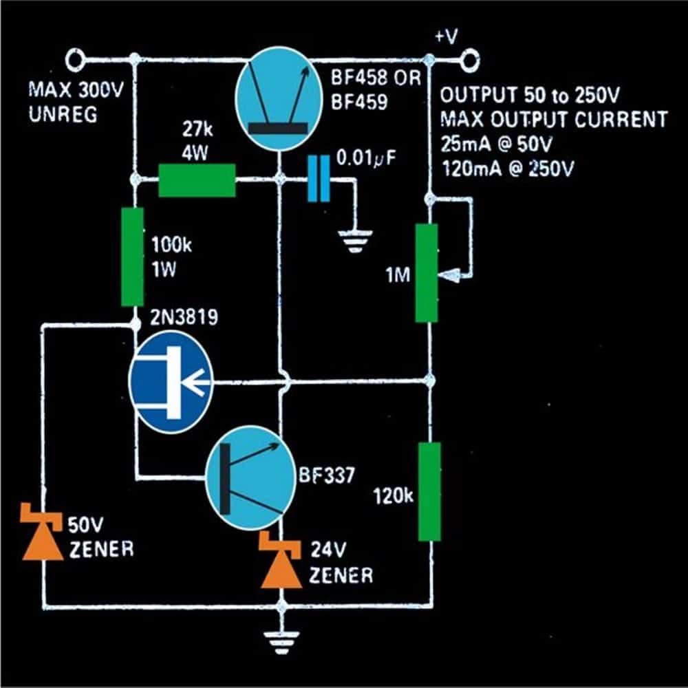
In this diagram we can see one main high voltage transistor BF458. That part is the main load handling device. So all the output current and voltage finally comes through this BF458. We can say this is the main power transistor of the whole setup.
Now how we control this transistor BF458? That is done using another small but high voltage transistor called BF337. This second transistor is placed in such a way that its emitter is clamped to a fixed 24V. That means even if the rest of the circuit is changing, the emitter of BF337 stays stuck at 24 volts.
So now what happens is, if we control the base current of BF337, then we can also control how much it allows current to flow through its collector. And this collector is finally connected to base of BF458. That means BF337 is like... it controls the base of BF458.
Now we use one FET along with a 1M potentiometer (variable resistor). This FET controls how much current is allowed to go into base of BF337.
So by adjusting the 1M pot, we can change the gate voltage of FET and that will change how much base current reaches BF337. Then BF337 controls BF458 and finally the output voltage and current changes smoothly.
So this whole thing becomes a nice chain:
Pot → FET → BF337 → BF458 → Output voltage
How We Power This Circuit?
The input AC 220V is taken directly from mains, and it is first passed through a bridge rectifier, just like before. After that we connect one 10uF / 400V capacitor to filter the DC and smooth out the rectified voltage.
This DC now becomes the input for our transistor circuit.
Big Warning – This Circuit Can Kill
Now again, one very important point which we should not forget: this circuit is totally non-isolated, that means the full 220V AC is present inside all parts of the board. There is no transformer to separate it from the dangerous mains.
So when we touch any wire or component even by mistake while it is ON, that shock can be fully lethal. It can kill instantly. So we should be super careful when making this, and while testing it.
Always test this with proper rubber gloves, one hand behind your back, dry wooden table, and full protection.
So that is how this transistor-FET based transformerless 0 to 300V variable supply works and gives us a controlled high voltage DC output with just few parts – but full danger if not handled with care!
Please is there any PCB schematic design?
Thank you
sorry, there’s no pcb…
Thank you
If I beef up the compoents to 600 or 800 volt ratings and higher current ratings, use a rheostat instead of a potentiometer can I have 0 to 600 volt regulated supply rated for 1000 mA, and if I use a P channel MOSFET and flip the Zener over can I get a NEAGTIVE regulated voltage supply? I want 0 to +600 VDC @ >1500mA, 0 to +600 VDC @ 200mA and 0 to -150 VDC @ ~50 mA for a vacuum tube tester. Yes I will have to use heat sinks?
Yes, that’s feasible, and rheostat is not required, you get it even with a small potentiometer.
Yes, changing he device polarities will give you negative voltage output, make sure to change the polarity of each semiconductor device used in the circuit…
Hi, I need something similar to this to fix a machine in my hobby shop that has failed. Is it possible to take 220 AC input, change it to DC, and have a variable amp control up from 0- 20 amps DC ?
Hey Wayne, 20 amp is huge and not recommended for capacitive power supplies, you will need an SMPS for that!