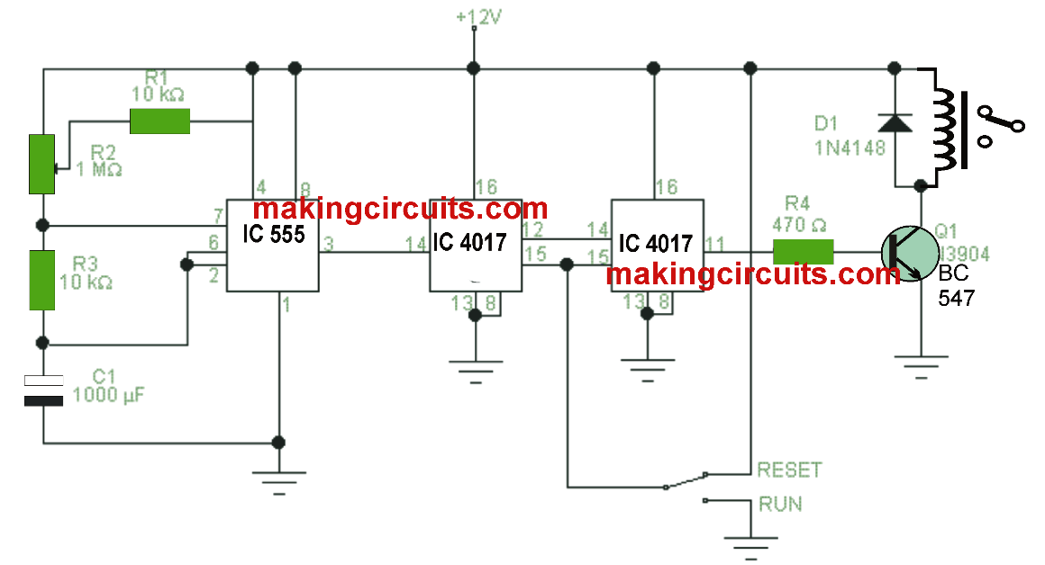
This circuit switches ON/OFF a load by means of an attached relay, that is triggered dependant upon the programmed time. As soon as the switch is powered to RUN, the counting down commences, initiating the triggering and switching of the load once the period has finished.
Its benefit over many timers is that, we learn with easy circuits regarding the potential of encoding long range time intervals. Using the values of the components which can be found in the circuit and determining the potentiometer R2 within each of its two opposites, we attain time intervals from 6 minutes to approximately 5 hours.
This circuit is dependent on an oscillator constructed from a clock with 555, on which the frequency could be adjusted through the potentiometer R2, which is exactly what specifies the timing. Right after the clock we see a couple of decoder circuits attached in cascade where each one splits the input frequency by 10, therefore then, we ultimately get a frequency divider through 100.
With switch SW1 we are able to disrupt the time period count up and reboot it whenever necessary. Once the clock frequency is greater than 100 pulses, the greatest range output of the final integrated circuit is scheduled to higher level, switching ON the transistor Q1 which initiates the relay and thus its contacts and the load.
Based on the relay we are able to hook up loads from 1 amp to 10 amps, which include heaters, light bulbs, sealing resistors, bells, etc.

1000ufကေလVoltဘယ္ေလာက္လဲ
2 times the supply voltage (rule of thumb)….= 25V