• Skip to main content
  • Skip to primary sidebar

Making Easy Circuits

Learn and build electronic circuits

You are here: Home / Sensors and Detectors / 10 Channel Capacitive Touch Switch Circuit

10 Channel Capacitive Touch Switch Circuit

Last Updated on November 17, 2024 by Admin 2 Comments

In this article we are going to construct a capacitive touch switch circuit with 10 channel output, the state of the each channel can be turned ON and OFF sequentially by touching acoin sized metal plate.

Capacitive touch is very commonly used in our smartphones, tablets or any gadgets which have touch screen. The term “capacitive” means charge, any smartphone or any gadgets say the term capacitive touch; it works by detecting charges around the screen.

When we touch any part of the screen there will be change in electrostatic charge, this information is processed by the microprocessor inside your smartphone.

Before the smartphone era most of us would have used a phone with touch screen which is much harder to navigate through the user interface (UI) and we have to apply force to select an item.

This type of touch screens is called resistive touch. They don’t work as smooth as capacitive touch.

They have two layers whichare coated with conductive material.When two layers come in contact a touch is registered and the microprocessor will receive this information and executes rest of the process.

In this 10 channel capacitive touch switch circuit project we are dealing with touch switch which operate similar to capacitive touch.

In capacitive touch the change in electrostatic charges are used to detect touch, but in our project, charges from the surrounding are injected into the circuitthrough our hand and this register a touch.

The circuit:

10 Channel Capacitive Touch Switch Circuit

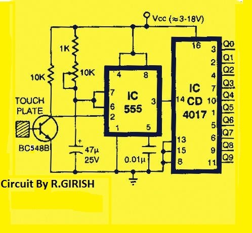
Initially pin#3 will be high and rest of the pins are low.When we touch the touch plate, pin#2 turns high and rest of the pins to low and touching it again turns pin#4 highand rest of the pins to low and so on (Q0 to Q9) sequentially .

The transistor detects the injected charge and amplifies. The touch signal is fed to IC 555 which is configured in mono stable mode. The IC555 generate clock pulses necessary to change the state of 10 pins in IC 4017.

You can connect MOSFETs or transistor or any other peripherals according to your customized needs.

You'll also like:

  • 1.  Non-Contact AC Mains Tester Circuit
  • 2.  Current Detector Circuit on PCB Tracks
  • 3.  Simple PIR Water Sprinkler Circuit
  • 4.  How to Build a Thunder Lightning Detector Circuit
  • 5.  Liquid Level Sensor Circuit
  • 6.  Find Concealed Metal Pipes, Nails, Studs using this Circuit

About Admin

Hey friends, Thanks a bunch for stopping by this site! I am an engineer with a Bachelor of Engineering in Electronics and Telecommunication. One of my passions is gathering information from all sorts of electronics books and tutorials. I then take that information and compile it into a language that is super easy to understand. My goal is to make those complex electronics circuit concepts and technical terms much more accessible for all the new and budding electronics engineers out there. I can also design customized circuit diagrams as required by the users.
If you have any questions related to this field, please do not hesitate to drop a comment! I am always here and ready to help you out with any queries you might have. I cannot wait to hear from you!

Reader Interactions

Comments

  1. Simon says

    April 26, 2019 at 2:41 pm

    Thank you for the 10 channel circuit but it seem the IC CD 4017 (Hex D-Type Flip-Flop) is the wrong number. Kindly provide the correct part no. Appreciate.

    Reply
    • admin says

      April 28, 2019 at 12:18 pm

      Use any IC 4017 which is a Johsons divide by 10 decade counter IC

      Reply

Leave a Reply Cancel reply

Your email address will not be published. Required fields are marked *

Primary Sidebar

Categories

  • 3 Phase (4)
  • 8051 Microcontroller (1)
  • Arduino (11)
  • Audio and Amplifier (102)
  • Automation (8)
  • Battery Chargers (64)
  • Bicycle Projects (4)
  • Car and Motorcycle Projects (39)
  • Datasheets (10)
  • DIY Projects (5)
  • Electrical (15)
  • Free Energy (6)
  • Games Projects (2)
  • High Voltage (14)
  • Hobby Projects (30)
  • Household Circuits (2)
  • IC 555 Circuits (4)
  • Ignition Circuits (2)
  • Indicators (50)
  • Infrared (6)
  • Inverter Circuits (29)
  • Lights and Lamps (97)
  • Medical (8)
  • Meter and Tester Circuits (38)
  • Motor Driver (17)
  • New Circuits (56)
  • Oscillators (30)
  • Pets and Pests (5)
  • Power supply (81)
  • Protection Circuits (25)
  • PWM (8)
  • Remote Control (20)
  • Security and Alarm Circuit (48)
  • Sensors and Detectors (66)
  • Signal Processor (23)
  • Solar Controller Circuits (61)
  • SSR (3)
  • Temperature Controller (20)
  • Timer (25)
  • Transformerless (7)
  • Transmitters (12)
  • Tutorials (45)
  • UPS (2)
  • Voltage Regulators (57)
  • Water Sensor and Controller (29)
  • Home
  • Privacy Policy
  • Contact
  • Disclaimer
  • Copyright

© 2025 · Making Easy Circuits