In this post we will see how we can make a very simple solar-powered LED system which also has a battery charging feature. This circuit will help us light up high-power LED (SMD) lights and the power can be anywhere from 10 watts to 50 watts, so we can decide as per our need.
Now we must protect our SMD LEDs, otherwise they can heat up too much or get too much current which can damage them. So here we are using LM338 IC which is cheap but works well for controlling current and keeping everything safe.
Ok, so this whole idea was actually requested by Mr. Mathew, who wanted a working solution for his problem.
How the Circuit Works
Here in this solar LED circuit diagram as shown below which is made for 10 watts to 50 watts LED operation, we can see some important stages that work together to make the system automatic.
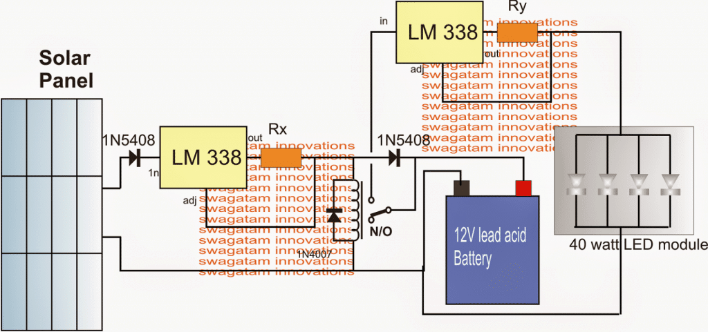
First we have a solar panel which is the main power source for this whole system.
Then we have two LM338 circuits which are working as current controllers so that the battery and LEDs get only the correct current, not too much, not too less.
Next we have a relay which is an automatic switch that helps us turn ON the LEDs at night and turn them OFF in the morning.
We also have a rechargeable battery which will store solar power and then use it at night for lighting up the LEDs.
Finally we have a 40-watt LED module which is the main light source that we want to turn ON at night.
Now we will see how all these parts are connected together and how they work in a sequence.
Ok so both LM338 ICs are connected in the same way, like current regulators. This means that they are using special resistors to measure and control current so that the battery and LEDs do not get extra current and stay safe.
Now the first LM338 circuit is responsible for charging the battery. It takes power from the solar panel and feeds it into the battery safely.
We have a resistor Rx in this circuit which is carefully selected so that the battery gets only the correct charging current. This prevents overcharging, which can damage the battery.
Now the second LM338 is handling the LED module. But here also we have another resistor Ry which makes sure that the LEDs get only the required current. If we do not control this, then LEDs can overheat and burn out which is known as thermal runaway.
The solar panel that we use should have a voltage between 18V to 24V so it can charge the 12V battery properly without any issues.
| Component | Specification | Quantity | Remarks |
|---|---|---|---|
| Solar Panel | 18V to 24V, minimum 5A capacity | 1 | Higher wattage for faster charging |
| Voltage Regulator | LM338 IC | 2 | One for battery, one for LED |
| Heatsink | Large aluminum heatsink | 2 | Required for LM338, prevents overheating |
| Resistor Rx | 0.31 ohms, 5 watts | 1 | Limits battery charging current |
| Resistor Ry | 0.4 ohms, 4 watts | 1 | Limits LED current |
| Diode | 1N5408 (3A or higher) | 2 | Blocks reverse current |
| Diode | 1N4007 | 1 | Relay switching protection (optional) |
| Battery | 12V Lead Acid, 40Ah or higher | 1 | Higher Ah gives longer backup |
| LED Module | 40W High Power LED | 1 | Can use 10W, 20W, or 50W as well |
| LED Heatsink | Large aluminum heatsink | 1 | Prevents LED overheating |
| Relay | 12V SPDT Relay, 5A or higher | 1 | Controls LED switching at night |
| Switch | N/O (Normally Open) Switch | 1 | For manual testing (optional) |
| Capacitor | 1µF, 50V Electrolytic | 1 | For LM338 stability |
| Capacitor | 1000µF, 16V Electrolytic | 1 | Smoothing rectifier output (optional) |
| Wires | Thick copper wires | As needed | Should handle 5A or more |
| Connectors | Screw Terminals | As needed | Easy connection for components |
| Insulation | Heat Shrink Tubes, Electrical Tape | As needed | For safety and durability |
Step-by-Step Construction Tips for the Solar LED and Battery Charger Circuit
Step 1: Get All the Parts Ready
Ok so first, we must collect all the necessary components like the solar panel, LM338 ICs, diodes, resistors, relay, battery, and LED module. If we do not have everything in place then we may struggle later while assembling the circuit.
Step 2: Mount the LM338 ICs on a Heatsink
Now we take both LM338 ICs and fix them tightly on a heatsink because they become very hot when working. If we do not use a big enough heatsink then these ICs will overheat and then stop working or even burn out.
Step 3: Connect the Solar Panel to the LM338 Charger Circuit
So now we take the solar panel output wires and connect them to the input pin of the first LM338 IC. But wait we must first add a 1N5408 diode in series so that power only flows in one direction and the battery does not discharge back into the panel at night.
Step 4: Attach the Battery to the LM338 Charger Output
Now we take the output of the first LM338 circuit and connect it to the 12V battery terminals. But we must also add a correctly calculated Rx resistor here which makes sure that the battery gets only the safe charging current. If we ignore this then the battery can get damaged quickly due to overcharging.
Step 5: Connect the Second LM338 to the LED Module
Next we take the second LM338 circuit and we connect its input to the battery terminals. The output of this LM338 goes directly to the LED module, but again we must add the correct Ry resistor so that the LEDs do not get excessive current.
Step 6: Insert the Relay for Automatic Switching
Ok now we take a 12V relay and we connect its coil to the solar panel. This is important because we want the relay to be ON during the day and OFF at night. The relays N/O (Normally Open) contacts should be connected between the battery and the LED module. This way during the day, the relay will keep the LEDs OFF and at night, the relay will switch ON the LEDs automatically.
Step 7: Fix All the Wires and Connections Properly
Now we must double-check all the connections and make sure there are no loose wires. We should solder all the points properly or else the circuit might work erratically and may even stop working after some time.
Step 8: Insulate and Secure Everything
After we finish wiring, we must cover all exposed metal connections with electrical insulation tape or heat-shrink tubing. If we leave them open then there can be short circuits, sparks, or even fire.
Step 9: Place the Solar Panel in a Good Position
Now we must install the solar panel at the right angle where it can get maximum sunlight during the day. If we place it in the wrong spot or at the wrong angle then the battery will not charge properly and the system will not work well at night.
Step 10: Test Everything Before Finalizing
Before we say “job done” we must test the whole circuit carefully. We check:
✔ Is the battery charging properly?
✔ Does the relay turn OFF the LED during the day?
✔ Do the LEDs turn ON automatically at night?
✔ Are the LM338 ICs getting hot, or do they stay cool with the heatsink?
Once everything is working correctly then we can finally secure the circuit inside a waterproof box so that it stays safe from dust, rain, and moisture.
Calculating the Current Limiting Resistors
Ok now let’s see how we calculate the resistor values for this circuit so that everything runs safely and nothing overheats or burns out.
Step 1: Formula for the Resistors
So for limiting the battery charging current we use this formula:
Rx = 1.25 / battery charging current
And for limiting the current to the LED module we use this one:
Ry = 1.25 / LED current rating
These formulas come from the current regulation method of the LM338 IC, so we must follow them properly to get the correct resistor values.
Step 2: Calculating the Battery Charging Resistor (Rx)
Now lets assume we are using a 40Ah lead-acid battery. Normally a good charging current for this kind of battery should be 10% of its capacity which is 4A.
So now we calculate Rx:
Rx = 1.25 / 4
Rx = 0.31 ohms
But wait! We must also check the wattage rating of this resistor otherwise it may overheat and burn.
Wattage = 1.25 × 4
Wattage = 5 watts
So we must use a 0.31-ohm resistor with at least a 5-watt power rating, or else it may not survive for long.
Step 3: Calculating the LED Current Resistor (Ry)
Now, let’s check the LED module side. We assume the LED module is 40 watts and it runs at 12V.
To find its current consumption we use this simple rule:
LED current = LED wattage / LED voltage
LED current = 40 / 12
LED current = 3.3A
So now we calculate Ry:
Ry = 1.25 / 3.3
Ry ≈ 0.4 ohms
Again we must check the wattage rating:
Wattage = 1.25 × 3.3
Wattage ≈ 4 watts
So we need a 0.4-ohm resistor with at least a 4-watt power rating to keep things safe.
Step 4: What About 10W LEDs?
Now if we use 10W LEDs then limiting resistors are not needed. Why? Because the battery voltage is already 12V which is exactly what the LEDs need. There is no risk of overcurrent so we don’t have to add an extra resistor in this case.
Leave a Reply