The discussed 110V, 220V voltage regulator circuit can be used for controlling or adjusting all high voltage level inputs such as 110V or 220V simply by altering a couple of resistor values. Here R6, and R7 can be effectively tweaked for getting any desired voltage output conversion from zero to 220V or even higher, with respect to the input supply level.
Presently there are numerous circuits intended for low voltage regulators. For higher voltages, for example supplies for valve circuits, the problem is unique.
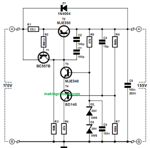
That certainly is why we chose to design this particular easy regulator that may manage these types of voltages. Typically the regulator includes simply three transistors. A 4th continues to be included for the current restricting purpose.
The circuit is really a positive series regulator, employing a pnp transistor (T2) to maintain the voltage drop as minimal as it can be. The procedure of the circuit is extremely simple.
Once the output voltage falls, T4 drags the emitter of T3 lower. That turns T2 harder ON, leading to the output voltage to elevate yet again. R4 confines the base current of T2. C1 and C2 happen to be included to enhance the steadiness of the circuit. They are attached in series in order that the voltage throughout each capacitor at switch-on or within a short circuit does not necessarily turn out to be overly substantial. You need to use capacitors ranked no less than 100 V for C1-C3.
D1 shields T2 against negative voltages that could appear once the input is short-circuited or even when large capacitors tend to be coupled to the output. We utilize a couple of zener diodes of 39 V hooked up in series for the reference voltage, offering 78 V for the base of T3. Simply because R6 is identical to R7 the output voltage is going to be two times as big, that is around 155 V.
T4 will act as a buffer for potential divider R6/R7, meaning we are able to make use of larger values for these resistors and the voltage is just not impacted by the base current of T2 (this current is around identical to the emitter current of T3).
This really is naturally not a temperature reimbursed circuit, however for this particular objective it is sufficient. Circuit diagram:Circuit diagramThe current restricting segment constructed about T1 could not be simpler.
Once the output current goes up over 30 mA the voltage around R1 brings about T1 to conduct. T1 after that restricts the base-emitter voltage of T2. R2 is necessary to safeguard T1 against incredibly quick peak voltages throughout R1. R3 is required to start out the regulator. With no R3 there would not be a voltage at the output and therefore there would not be a base current within T2.
R3 allows T2 carry out slightly, which can be adequate for the regulator to achieve its expected condition. Throughout normal procedure having a voltage drop of 15 V over T2 and a current of approximately 30 mA you don't need to for added cooling of T2.
The junction temperature can now be 70 °C, and that means you may melt away your fingers if you are not really cautious! The lower the input voltage is, the greater current may be furnished by this regulator.
This current depends on the SOAR (Safe Operation ARea) of T2. Within a short circuit and also an input voltage of 140 V the current is approximately 30 mA and T2 undoubtedly needs a heatsink of no less than 10 K/W in such circumstances.
To improve the output voltage you need to use a bigger value for R6. If you wish to make use of a higher reference voltage, you ought to substitute T4 with a MJE350. In case you just ever need to pull just a few milliamps you don't need to to incorporate T4 and R4. The potential divider (R6/R7) then can be attached straight to the emitter of T3.
The ripple reductions in the proposed 110V, 220V voltage regulator circuit is approximately 50 dB. The quiescent current is 2.5 mA and for smaller currents the dropout voltage is barely 1.5 V.
Courtesy: Elektor Electronics Magazine
Leave a Reply