In this post we are looking at one cheap Chinese made 12V 1 amp MOSFET based smps circuit. We are trying to see how it is made and also how you can change it to make 24V 1 amp smps or 12V 2 amp smps.
This change is possible because the main parts inside are strong enough so that when you change some values then it can handle the higher voltage or higher current without making trouble. So we are going to check this small smps in detail.
About the mosfet
The MOSFET that is used inside this circuit is STB9NK60Z. This MOSFET is not some simple weak device but it is one highly advanced and rugged 600V 7A type.
It is specially made for those circuit situations where the voltage can suddenly rise and behave in unpredictable way.
This kind of MOSFET can tolerate high spikes and sudden voltage changes without damage. That is why it is used here because even if the smps is cheap, this part can make it run safely in high voltage environment.
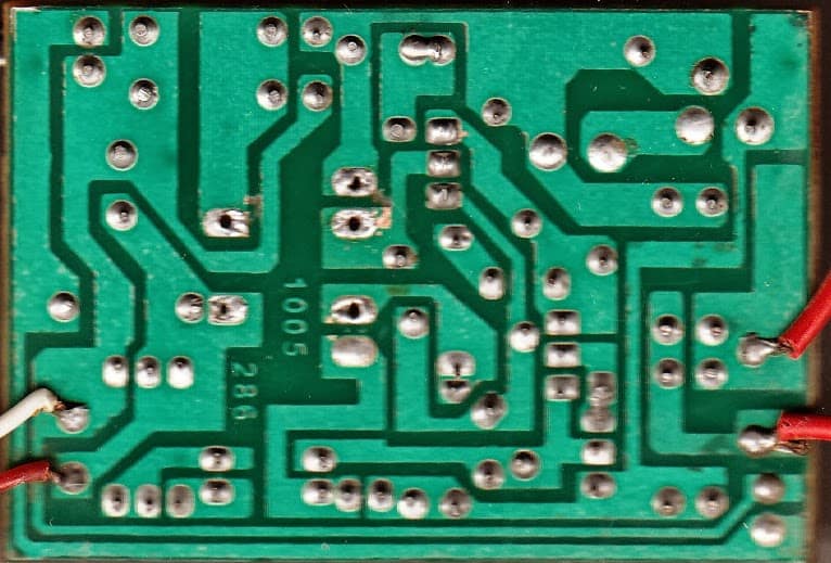
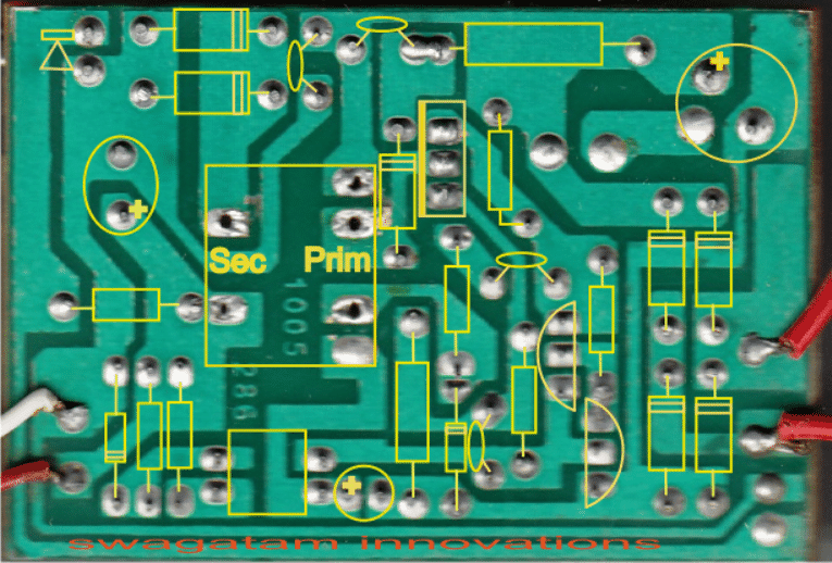
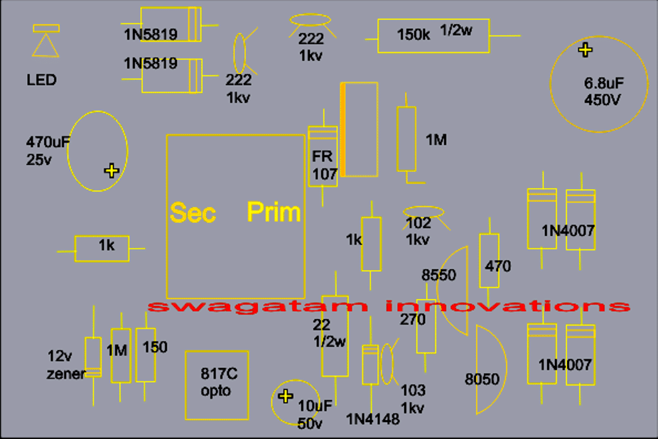
Reverse Engineering a 12V 1 Amp SMP Adapter Physically
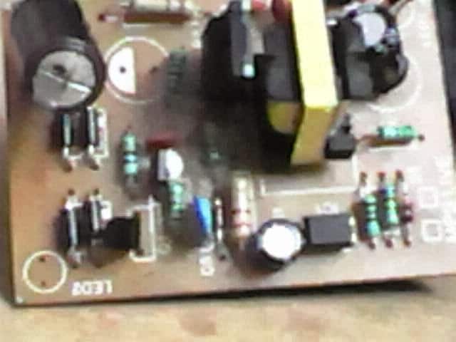
Coil Details:
The circuit we are talking about of a 12V, 1 amp MOSFET based smps circuit utilizes a single E-core transformer, the winding details may be understood from the following info:
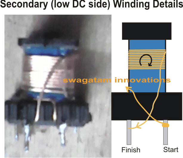
Wire thickness we need for the above secondary winding = 0.6mm, no. of turns = 12
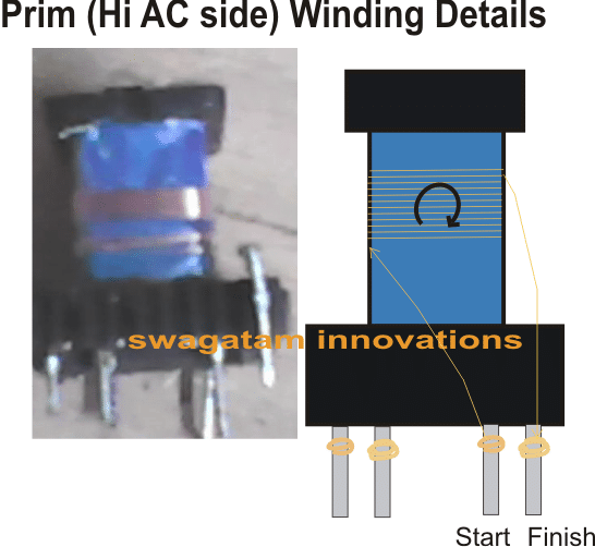
Wire thickness we need for the above primary winding = 0.25mm, no. of turns = 12
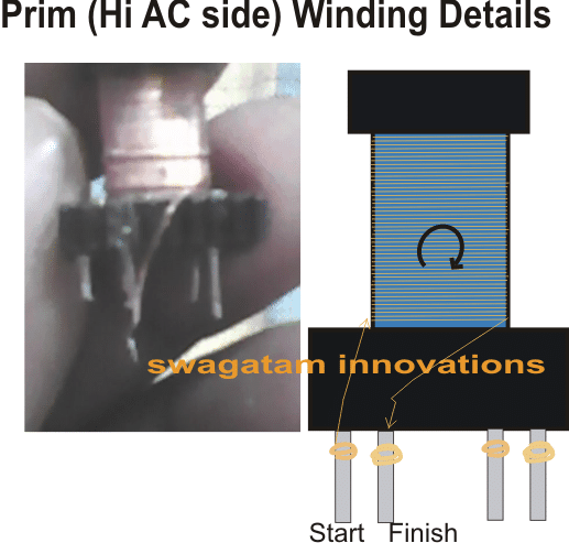
Wire thickness for the above primary winding = 0.25mm, no. of turns = 170
Feedback story from Mr.Dev
We got one feedback from our dedicated reader Mr Debabrata Mandal. He told that he bought one smps today which is almost exactly same like the one in our post, cost him around 100₹.
He tested it at the shop for around 10 seconds and it worked fine. He brought it home, plugged it in and was just going to test it with a multimeter when there was a popping sound, but the indicator LED was still glowing.
He opened it and saw that the electrolytic capacitor on the 12V side had blown and another 16V capacitor was burnt.
Even in this condition he tested the output and saw that it was around 22 to 23V. Right now he cannot check it properly because when he turns it on then within a second the MOSFET starts becoming burning hot.
He also cannot figure out the transistor types S9014 and S8550 and their pin configuration.
He said there are only three components different from our design. A 100E 0.5W resistor instead of our 150E 0.5W resistor, a 220E resistor instead of our 270E resistor and an S9014 transistor instead of our S8050 transistor.
Without removing any part from the board he tested the diodes and zener diodes and they looked fine. So he asked if without removing the transistor and MOSFET we can tell him how to check them without switching on the power because switching on could melt the MOSFET for sure.
He also asked for any idea to debug and also how to tweak the circuit to get 14V (around 13.6 to 14.4) at 1.1A or more than 1.05A.
Possible solution
The MOSFET should normally not become hot if the output is not loaded or shorted. If it is getting hot without any load then that can mean the primary section is faulty.
To confirm this we can cut the PCB tracks from the secondary winding terminals so that it becomes totally isolated from the rest of the board, and confirm with a multimeter that it is isolated.
Next we connect a 25 watt bulb in series with the input AC to the smps and switch on power. If the bulb glows or if the MOSFET still gets hot then we can confirm a faulty primary stage.
Then we remove the transistors one by one, replace with new ones and apply the input voltage to check if the MOSFET condition changes. If the heating still remains then we finally replace the MOSFET itself.
Once these steps are completed and the primary problem is fixed then we can check why the secondary is generating 24V. This can happen if the winding data is wrong or it may just settle to the correct output once the primary is working fine.
More inputs from Mr. Dev
Mr Dev then said he already took out the 2 transistors, the MOSFET, and the transformer and checked them and they all looked fine. He also checked the resistors and capacitors and they seemed fine. He put them back and started checking the PCB carefully.
He found that after soldering they did not cut one leg short, so it protruded and touched the copper film causing a short.
He cut that leg short and checked again and the output now showed 2.3V but still the MOSFET was getting hot.
Finally with nothing else to do he replaced the blown capacitor with a 1000uF 16V Keltron capacitor and surprisingly the problem got fixed.
Analyzing the issue
So the problem was in the filter capacitor. When it was faulty the opto-coupler could not receive proper feedback from it so the MOSFET conduction was not regulated.
After replacing the capacitor the opto-coupler could work correctly and regulate the MOSFET. That fixed the heating problem and the circuit started working fine. So in the end everything turned out fine.
Please, I need a transformer for my project with the following voltage and power:
1. Secondary:600Volt,230Volt and 0Volt,12Volt and 0Volt
2. Primary:18Volt,12Volt Center tap
Power rating:5000 Wat
Please, what should be the turns for both primary and secondary and should be the wire gauge and also the size of the plate? Thanks.
Hi Daniel,
Can you please post your question under this video, I will try to solve it quickly with full details:
https://youtu.be/cVmbcm0eCG4