• Skip to main content
  • Skip to primary sidebar

Making Easy Circuits

Learn and build electronic circuits

You are here: Home / New Circuits / How to Build a 12V Car Laptop Charger Circuit Using Boost Converter

How to Build a 12V Car Laptop Charger Circuit Using Boost Converter

Last Updated on February 17, 2018 by Admin Leave a Comment

The submit talks about a basic enhance converter circuit for charging laptops from a 12V car battery.


buck2Bconverter
The recommended inverter circuit is definitely a just simply boost converter unit created for producing the necessary laptop charging voltage.
A basic boost converter can be created utilizing the IC 555, I probably have talked about it by means of various other articles within this site.
As might be observed right here figure, an easy yet very economical boost converter circuit could be designed for making use of with laptops from any specific high current source acquiring a lower voltage than the laptop charging level.


Switch Mode 12V Car Laptop Charger Circuit Using Boost Converter
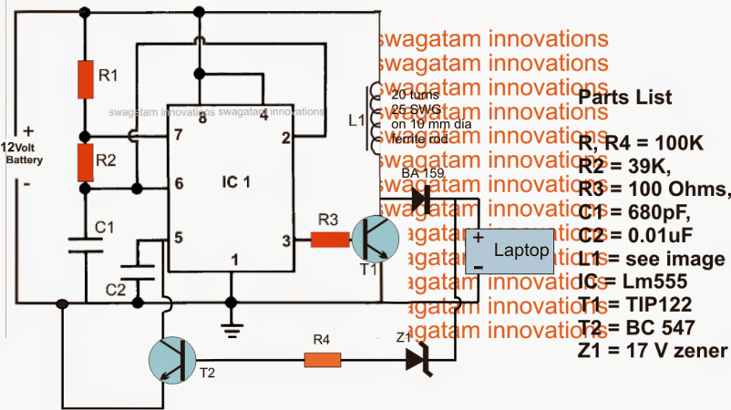
The numerous phases incorporated in the above 12 V laptop boost charger circuit could be recognized given below:
IC1 which happens to be a 555 IC is set up as a regular astable for producing a dependable specific frequency at the rate of 12 kHz which can be obtained at pin3 of the IC.
The above high frequency output is provided to the base of a driver BJT T1 for activating the above frequency with high current in L1.
On account of the inherent property of the inductor L1, throughout every OFF time of T1, the exact quantity of stimulated voltage is kicked back from the inductor L1 and provided to the load attached at the output via the fast recovery diode BA159.
The load the following is the laptop which allows the enhanced voltage for charging its internal battery.
Given that the laptop may need an accurate 19 to 20V for the functions, the output from L1 has to be controlled and stabilized to be able to render things secure for the associated laptop battery.
The above measures is looked after by presenting T2 and the connected R4 and Z1 elements.
Z1 is chosen to be precisely equivalent to the laptop charging voltage that is at 20 V (17V is incorrectly demonstrated in the diagram).
At any time the output tends to drift away from this value, Z1 receives forward biased activating T2, which often grounds pin5 of the IC.
The above circumstance instantly decreases the IC 555 pin3 voltage to minimal levels for that specific on the spot until Z1 prevents carrying out along with the circumstance is restored to the safe zone....the switching is sustained at a swift speed preserving a continuing voltage for the laptop

You'll also like:

  • 1.  How to Make a Office Call Bell Network Circuit with LED Monitor
  • 2.  Easy FET Circuits you can Build and Use
  • 3.  Exploring a Bluetooth Headset
  • 4.  Easy 1.5V to 12V/24V Converter Circuits
  • 5.  How to Modify a Bluetooth Headset Device for Personalized Applications
  • 6.  Discotheque Music Level Indicator Circuit

About Admin

Hey friends, Thanks a bunch for stopping by this site! I am an engineer with a Bachelor of Engineering in Electronics and Telecommunication. One of my passions is gathering information from all sorts of electronics books and tutorials. I then take that information and compile it into a language that is super easy to understand. My goal is to make those complex electronics circuit concepts and technical terms much more accessible for all the new and budding electronics engineers out there. I can also design customized circuit diagrams as required by the users.
If you have any questions related to this field, please do not hesitate to drop a comment! I am always here and ready to help you out with any queries you might have. I cannot wait to hear from you!

Reader Interactions

Leave a Reply Cancel reply

Your email address will not be published. Required fields are marked *

Primary Sidebar

Categories

  • 3 Phase (4)
  • 8051 Microcontroller (1)
  • Arduino (11)
  • Audio and Amplifier (102)
  • Automation (8)
  • Battery Chargers (64)
  • Bicycle Projects (4)
  • Car and Motorcycle Projects (39)
  • Datasheets (10)
  • DIY Projects (5)
  • Electrical (15)
  • Free Energy (6)
  • Games Projects (2)
  • High Voltage (14)
  • Hobby Projects (30)
  • Household Circuits (2)
  • IC 555 Circuits (5)
  • Ignition Circuits (2)
  • Indicators (50)
  • Infrared (6)
  • Inverter Circuits (29)
  • Lights and Lamps (97)
  • Medical (8)
  • Meter and Tester Circuits (38)
  • Motor Driver (17)
  • New Circuits (56)
  • Oscillators (30)
  • Pets and Pests (5)
  • Power supply (80)
  • Protection Circuits (25)
  • PWM (9)
  • Remote Control (20)
  • Security and Alarm Circuit (48)
  • Sensors and Detectors (66)
  • Signal Processor (23)
  • Solar Controller Circuits (62)
  • SSR (3)
  • Temperature Controller (20)
  • Timer (25)
  • Transformerless (7)
  • Transmitters (12)
  • Tutorials (45)
  • UPS (2)
  • Voltage Regulators (57)
  • Water Sensor and Controller (29)
  • Home
  • Privacy Policy
  • Contact
  • Disclaimer
  • Copyright

© 2025 · Making Easy Circuits