• Skip to main content
  • Skip to primary sidebar

Making Easy Circuits

Learn and build electronic circuits

You are here: Home / Voltage Regulators / 2 in 1 Light Dimmer Circuit with Touch Pad Operation

2 in 1 Light Dimmer Circuit with Touch Pad Operation

Last Updated on April 8, 2020 by Admin Leave a Comment

Dimmer circuits are always very popular. The twin dimmer offers two independent controls in one unit.

A type S576 provides control of each section of the circuit. S576 is an advanced version of S566. The phase gating is controlled by this type of ICs by short or long command pulses. Those pulses emanate from a touch pad. However, the pulses shorter than 60 ms are considered as noise.

Short pulses between 60 to 400 ms cause the lamp to be turned on or off. That depends on whether it was on or off, respectively.

How the Circuit Works

If the touch pad is being touched for higher than 400 ms, the appropriate lamp is dimmed at a certain speed. When the finger is held on a touch pad, the lamp completely goes out and will slowly light up after that. When the finger is still on the pad, the light will begin to dim again, even if it was primarily at its full brightness.

rwin light dimmer circuit

The S576 is available in three versions, namely A, B and C. In A and C version, the lamp is always turned on or off half-way between in the middle of maximum and minimum brightness before it can be dimmed. On the other hand, the B version remembers the last level of brightness, to ensure that the lamp is always turned on or off in the last brightness condition. This is why version B is more fascinating. Such various possibilities have been summed up is figure 1.

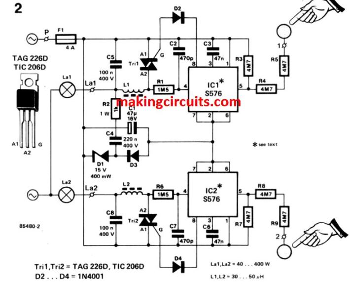
The circuit of the twin dimmer is shown in the second figure. Power for the ICs is provided via R2, C4, D1 and D3. C1 smoothens the supply. The speed with which the lamp gets dimmer or brighter is determined by two capacitators, namely C3 and C6.Onto the printed circuit board, the twin dimmer is can be built in the best way – this has been shown in the third figure. It was the intention to fir the board onto a standard round junction box. Due to which it is evidently necessary that the components used to build the twin dimmer must have correct size as shown on the board.

The board is being connected to the lighting system via three terminals, namely L to the live wire; and Si and S2 to the lamp’s switching wire. The lamp’s junction is already connected to neutral. It must be noted that the dimmers must not be used with neon tubes.

You'll also like:

  • 1.  How to Build a LM317 as a Variable Voltage Regulator and Variable Current Regulator
  • 2.  Simple Boost Converter Circuit
  • 3.  110V, 220V Voltage Regulator Circuit
  • 4.  High Power Triac Dimmer Circuit for 1000 watt Loads
  • 5.  High Current LM317 Variable Power Supply Circuit
  • 6.  How Triacs Work: Explained

About Admin

Hey friends, Thanks a bunch for stopping by this site! I am an engineer with a Bachelor of Engineering in Electronics and Telecommunication. One of my passions is gathering information from all sorts of electronics books and tutorials. I then take that information and compile it into a language that is super easy to understand. My goal is to make those complex electronics circuit concepts and technical terms much more accessible for all the new and budding electronics engineers out there. I can also design customized circuit diagrams as required by the users.
If you have any questions related to this field, please do not hesitate to drop a comment! I am always here and ready to help you out with any queries you might have. I cannot wait to hear from you!

Reader Interactions

Leave a Reply Cancel reply

Your email address will not be published. Required fields are marked *

Primary Sidebar

Categories

  • 3 Phase (4)
  • 8051 Microcontroller (1)
  • Arduino (11)
  • Audio and Amplifier (102)
  • Automation (8)
  • Battery Chargers (64)
  • Bicycle Projects (4)
  • Car and Motorcycle Projects (39)
  • Datasheets (10)
  • DIY Projects (5)
  • Electrical (15)
  • Free Energy (6)
  • Games Projects (2)
  • High Voltage (14)
  • Hobby Projects (30)
  • Household Circuits (2)
  • IC 555 Circuits (5)
  • Ignition Circuits (2)
  • Indicators (50)
  • Infrared (6)
  • Inverter Circuits (29)
  • Lights and Lamps (97)
  • Medical (8)
  • Meter and Tester Circuits (38)
  • Motor Driver (17)
  • New Circuits (56)
  • Oscillators (30)
  • Pets and Pests (5)
  • Power supply (80)
  • Protection Circuits (25)
  • PWM (9)
  • Remote Control (20)
  • Security and Alarm Circuit (48)
  • Sensors and Detectors (66)
  • Signal Processor (23)
  • Solar Controller Circuits (62)
  • SSR (3)
  • Temperature Controller (20)
  • Timer (25)
  • Transformerless (7)
  • Transmitters (12)
  • Tutorials (45)
  • UPS (2)
  • Voltage Regulators (57)
  • Water Sensor and Controller (29)
  • Home
  • Privacy Policy
  • Contact
  • Disclaimer
  • Copyright

© 2025 · Making Easy Circuits