We certainly have previously found in most of my previous posts precisely how triacs are utilized in electronic circuits for switching AC loads.
Triacs are fundamentally devices which are usually capable to turn on a specific connected load as a reaction to an external DC trigger.
Even though these types of might be integrated for whole turn on and complete turn off processes of a load, the device is furthermore widely employed for regulating an AC, such that the output to the load might be decreased to any preferred value.
For instance triacs are extremely widely used dimmer switch applications where the circuit is made to make the device switch in this way that it performs only for a specific portion of the AC sine wave and remains cut OFF during the leftover parts of the sine wave.
This outcome is an corresponding output AC which includes a standard RMS value more affordable than the actual input AC.
The associated load as well replies to this lower value AC and is thus managed to that specific consumption or subsequent output.
This is exactly what precisely occurs inside electrical dimmer switches which can be generally employed for managing ceiling fan and incandescent lights.
Basic and the Best Triac Dimmer Switch Circuit
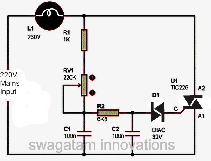
The circuit diagram presented above is an classic illustration of a dimmer switch, where a triac continues to be employed for managing the depth of light.
When AC mains is provided to the above circuit, as per the setting of the pot, C2 charges fully after a specific delay supplying the necessary firing voltage to the diac.
The diac performs and causes the triac into conduction, but this also releases the capacitor whose charge decreases below the diacs firing voltage.
Because of this the diac prevents carrying out and so does the triac.
Such things happen for each cycle of the mains AC sine wave signal, which cuts it into discrete sections, leading to well customized lower voltage output.
The setting of the pot sets the charge and the release timing of C2 which often chooses for how much time the triac stays in a carrying out mode for the AC sine signals.
Will probably be seeking to discover why C1 is put in the circuit, simply because the circuit would certainly work even without it.
It's accurate, C1 is definitely not needed if the associated load is a resistive load like an incandescent lamp etc.
In spite of this if the load is an inductive type, the inclusion of C1 evolves into extremely critical.
Inductive loads have a bad habit of getting back an element of the stored energy in the winding, back into the supply rails.
This scenario can block up C2 which then evolves into not able to charge correctly for starting the subsequent succeeding initiating.
C1 within this circumstance assist C2 to keep up is cycle by offering bursts of small voltages even though C2 has totally discharged, and thus keeps the proper switching rate of the triac.
Triac dimmer circuits have the property of producing a lot of RF disruptions in the air while working thereby an RC network turns into crucial using these dimmer switches for lowering the RF generations. The above circuit is demonstrated without the feature thereby will produce a number of RF which may interrupt advanced electronic audio systems.
The circuit of a dimmer switch noted below integrate the required measures for subsiding the above situation.
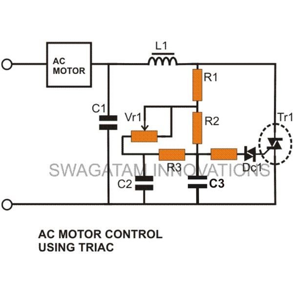
Parts List for the above improved fan dimmer circuit
C1 = 0.1u/400V
C2, C3 = 0.1/250V,
R1 = 15K,
R2 = 330K,
R3 = 33K,
R4 = 100 Ohms,
VR1 = 220K, linear
Diac = DB3,
Triac = BT136
L1 = 40uH
220 volt 2500 vat devre şeması varmi
do you have a schematic for a liquid level sensor that will turn a sump pump on at a high water level and off at a low water level?