• Skip to main content
  • Skip to primary sidebar

Making Easy Circuits

Learn and build electronic circuits

You are here: Home / Voltage Regulators / 220V Light Dimmer Circuit using Push Button Control

220V Light Dimmer Circuit using Push Button Control

Last Updated on January 10, 2018 by Admin Leave a Comment

The following circuit can be effortlessly used for dimming a 220V or 120V mains operated lamp or fan using a single push button operation.

mains light dimmer using push button

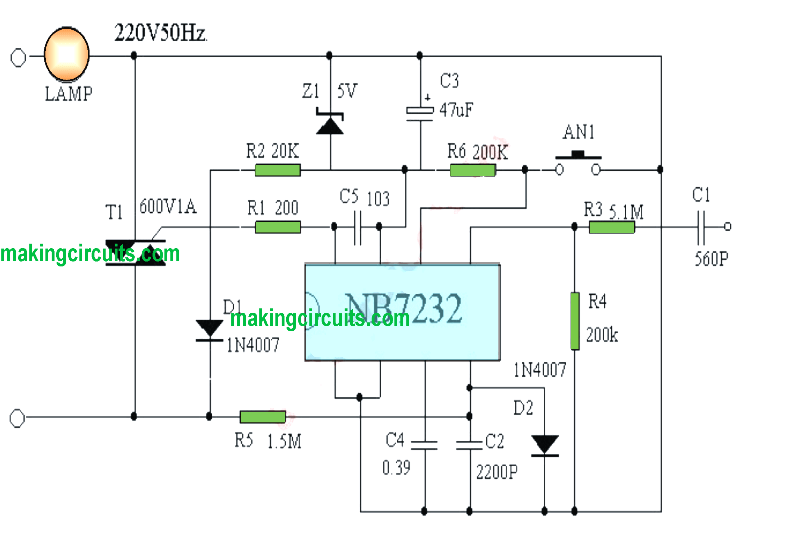
Referring to the given figure, the IC  NB7332 is an advanced frequency generator which changes its high frequency pulse range to alter the triac's switching pattern such that for lower power pulses with wider switching periods is employed, while for higher power the gaps between the frequency pulses are reduced proportionately.

The push button can be used for setting up the illumination level on the connected lamp or may be a ceiling fan.

Each press of the button causes a step wise power increase on the load and finally when the full power is reached the subsequent press on the button reverts the load intensity to zero, and the process initiates from there in the ascending order.

The IC NB7232 also enables an external triggered operation for the intended light dimmer operation from a remote source in order to achieve a remote controlled fan or light dimming operations. This trigger can e implemented across the end of the C1 capacitor.


If you have any doubts regarding this design make sure to ask them through your commentrs

You'll also like:

  • 1.  IC 7812, 7805 Current Booster Circuit
  • 2.  Simple Mains Overload Protection Circuit
  • 3.  Solid State 220V to 110V Converter Circuit
  • 4.  Generator Mains Power Booster Circuit
  • 5.  220V Touch Dimmer Switch Circuit with 4 Step Control
  • 6.  Designing a IC 723 Power Supply with Variable Voltage and Current

About Admin

Hey friends, Thanks a bunch for stopping by this site! I am an engineer with a Bachelor of Engineering in Electronics and Telecommunication. One of my passions is gathering information from all sorts of electronics books and tutorials. I then take that information and compile it into a language that is super easy to understand. My goal is to make those complex electronics circuit concepts and technical terms much more accessible for all the new and budding electronics engineers out there. I can also design customized circuit diagrams as required by the users.
If you have any questions related to this field, please do not hesitate to drop a comment! I am always here and ready to help you out with any queries you might have. I cannot wait to hear from you!

Reader Interactions

Leave a Reply Cancel reply

Your email address will not be published. Required fields are marked *

Primary Sidebar

Categories

  • 3 Phase (4)
  • 8051 Microcontroller (1)
  • Arduino (11)
  • Audio and Amplifier (102)
  • Automation (8)
  • Battery Chargers (64)
  • Bicycle Projects (4)
  • Car and Motorcycle Projects (39)
  • Datasheets (10)
  • DIY Projects (5)
  • Electrical (15)
  • Free Energy (6)
  • Games Projects (2)
  • High Voltage (14)
  • Hobby Projects (30)
  • Household Circuits (2)
  • IC 555 Circuits (5)
  • Ignition Circuits (2)
  • Indicators (50)
  • Infrared (6)
  • Inverter Circuits (29)
  • Lights and Lamps (97)
  • Medical (8)
  • Meter and Tester Circuits (38)
  • Motor Driver (17)
  • New Circuits (56)
  • Oscillators (30)
  • Pets and Pests (5)
  • Power supply (80)
  • Protection Circuits (25)
  • PWM (9)
  • Remote Control (20)
  • Security and Alarm Circuit (48)
  • Sensors and Detectors (66)
  • Signal Processor (23)
  • Solar Controller Circuits (62)
  • SSR (3)
  • Temperature Controller (20)
  • Timer (25)
  • Transformerless (7)
  • Transmitters (12)
  • Tutorials (45)
  • UPS (2)
  • Voltage Regulators (57)
  • Water Sensor and Controller (29)
  • Home
  • Privacy Policy
  • Contact
  • Disclaimer
  • Copyright

© 2025 · Making Easy Circuits